3 checking the commlink iv driver, Diagram, Overview – Auto-Zone Control Systems Auto-Zone Plus Systems Installation & Operation (Version 03A) User Manual
Page 162: Measurements, Action, Local loop acceptable range, Condition action
Section 4
Auto-Zone Plus
4-12
Start-Up and Troubleshooting
1.3.3
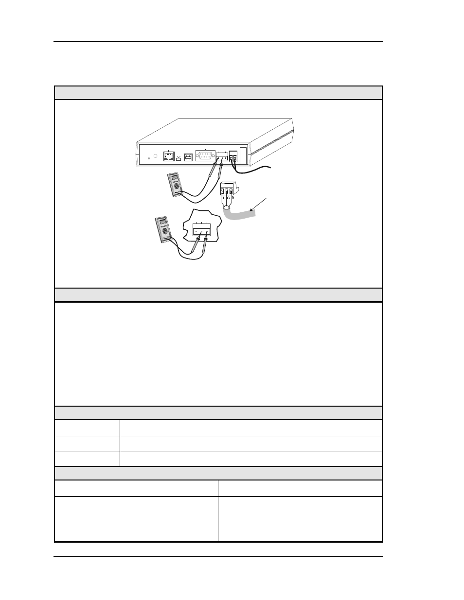
Checking the CommLink IV Driver
Diagram
Set Your Meter
To Read DC Volts
+
-
+
-
+
-
T-To-G
+3.1 VDC
To
+3.2 VDC
R-To-G
+3.4 VDC
To
+3.6 VDC
Communications
Loop
Disconnected
CommLink IV
To 24 VAC
Power Supply
MODEM
RS-232
Serial #
COMPUTER
USB
10/100
ETHERNET
DIAG
24V
T
T
G
G
R
R
GN
D
485 LOOP
485 LOOP
POWER
ACT
LNK
USB
Co
n
fi
g
No
rm
al
Overview
This test checks for proper Network loop voltages coming from the CommLink IV.
Tip: The Loop LED (located on the front panel) should “flicker” when the CommLink IV
is attempting to communicate. The Loop LED will flicker more noticeably for a few
seconds when first powered up. If the LED does not flicker, the unit is not
functioning.
Proper loop voltages are essential for reliable communications. It is normal to see
fluctuations at this point on the CommLink IV. The average value should be close to the
acceptable range described below. Values will vary upon initial powerup for about 10-15
seconds as the unit attempts to communicate.
Measurements
Local Loop
Acceptable Range
T - G (SHLD)
3.1 – 3.2 Volts DC
R - G (SHLD)
3.4 – 3.6 Volts DC
Action
Condition Action
If voltages are too high or too low on either
side
1. The CommLink IV has a damaged
comm driver chip. Replace the
CommLink IV. The driver chip is not
field replaceable.