5 vmebus p1 connector, Table 5-10, Com port connector pin assignments – Artesyn MVME3100 Single Board Computer Installation and Use (June 2014) User Manual
Page 97: Table 5-11, Vmebus p1 connector pin assignments, Vmebus p1 connector, Pin assignments
Pin Assignments
MVME3100 Single Board Computer Installation and Use (6806800M28E)
97
5.2.4
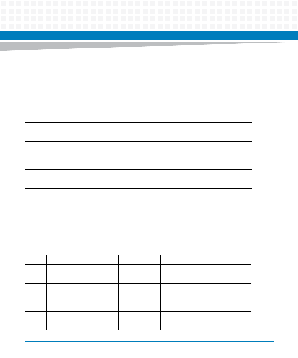
Serial Port Connectors (COM1/J41A, COM2–COM5/J2A-D)
There is one front access asynchronous serial port interface (SP0) that is routed to the RJ-45
front-panel connector. There are four asynchronous serial port interfaces, SP1 – SP4, which are
routed to the P2 connector. The pin assignments for these connectors are as follows:
5.2.5
VMEbus P1 Connector
The VME P1 connector is a 160-pin DIN. The P1 connector provides power and VME signals for
24-bit address and 16-bit data. The pin assignments for the P1 connector is as follows:
Table 5-10 COM Port Connector Pin Assignments
Pin
Signal
1
No connect
2
RTS
3
GND
4
TX
5
RX
6
GND
7
CTS
8
No connect
Table 5-11 VMEbus P1 Connector Pin Assignments
ROW Z
ROW A
ROW B
ROW C
ROW D
1
Reserved D00
BBSY*
D08
+5V
1
2
GND
D01
BCLR*
D09
GND
2
3
Reserved D02
ACFAIL*
D10
Reserved
3
4
GND
D03
BG0IN*
D11
Reserved
4
5
Reserved
D04
BG0OUT*
D12
Reserved
5
6
GND
D05
BG1IN*
D13
Reserved
6
7
Reserved D06
BG1OUT*
D14
Reserved
7
- ARTM-9405 16x10GbE Installation and Use Guide (May 2014) (64 pages)
- ATCA 7370 / ATCA 7370-S Installation and Use (January 2015) (256 pages)
- ATCA 7370 / ATCA 7370-S Installation and Use (September 2014) (254 pages)
- ARTM-831X Installation and Use (June 2014) (346 pages)
- ATCA-7350 - Integrating with Workbench User Guide (September 2014) (34 pages)
- ATCA-7350 Installation and Use (September 2014) (208 pages)
- ATCA-7365-CE Installation and Use (Jan 2015) (300 pages)
- ATCA-7365-CE Installation and Use (May 2014) (294 pages)
- ATCA-7365-CE Installation and Use (May 2014) (306 pages)
- ATCA-7368 Installation and Use (June 2014) (222 pages)
- ATCA-7475 Installation and Use (October 2014) (284 pages)
- ATCA-7480 Installation and Use (April 2015) (330 pages)
- ATCA-8330 Installation and Use (April 2015) (236 pages)
- ATCA-8320 Installation and Use (May 2014) (456 pages)
- ATCA-9305 User's Manual (May 2014) (270 pages)
- ATCA-9405 Installation and Use (October 2014) (168 pages)
- ATCA-F120 Installation and Use (August 2014) (122 pages)
- ATCA-F140 Installation and Use (September 2014) (138 pages)
- ATCA-MF106 Installation and Use (September 2014) (86 pages)
- Centellis-4440/AXP1440 Installation and Use (September 2014) (208 pages)
- Centellis 4410 (AXP-1410) Installation and Use (July 2014) (202 pages)
- Centellis 2100 Release 3.0 Installation and Use (March 2015) (192 pages)
- Centellis 2100 Release 3.0 Installation and Use (March 2015) (176 pages)
- Centellis 2000 User Card-10GE Installation and Use (May 2014) (54 pages)
- Centellis 2000 User Card-10GE with Telco Alarm Installation and Use (May 2014) (60 pages)
- COMX-CAR-210 Installation and Use (August 2014) (76 pages)
- COMX-P1022 Installation and Use (July 2014) (84 pages)
- COMX-P2020 Installation and Use (February 2015) (100 pages)
- COMX-CORE Series Installation and Use (August 2014) (128 pages)
- COMX-P2020 Installation and Use (July 2014) (100 pages)
- COMX-P4080-2G-ENP2 Installation and Use (August 2014) (70 pages)
- COMX-P4080 Installation and Use (August 2014) (126 pages)
- COMX-P40x0 ENP2 Installation and Use (August 2014) (130 pages)
- COMX-P40x0 ENP2 Installation and Use (January 2015) (140 pages)
- iVPX7225 RTM Installation and Use (April 2015) (56 pages)
- MITX-430/MITX-440-DVI-2E Installation and Use (August 2014) (118 pages)
- CPCI-6200 Installation and Use (May 2015) (234 pages)
- SCP-MITX-CORE-820-SM Installation and Use (August 2014) (132 pages)
- iVPX7225 Installation and Use (April 2015) (168 pages)
- MVME2502 Installation and Use (August 2014) (150 pages)
- MVME2502 Installation and Use (December 2014) (166 pages)
- MVME2500 VxWorks 6.8 AMP User Guide (August 2014) (40 pages)
- MVME2500 VxWorks 6.8 User Guide (April 2014) (44 pages)
- MVME4100 Single Board Computer Installation and Use (June 2014) (136 pages)