4 pmc i/o voltage configuration, 5 rtm seeprom address switch (s1), Table 1-5 – Artesyn MVME3100 Single Board Computer Installation and Use (June 2014) User Manual
Page 30: Rtm eeprom address switch assignments, Table 1-6, Eeprom address settings, Hardware preparation and installation
Hardware Preparation and Installation
MVME3100 Single Board Computer Installation and Use (6806800M28E)
30
1.4.4
PMC I/O Voltage Configuration
The onboard PMC sites may be configured to support 3.3V or 5.0V I/O PMC modules. To
support 3.3V or 5.0V I/O PMC modules, both PMC I/O keying pins must be installed in the
holes. If both keying pins are not in the same location or if the keying pins are not installed, the
PMC sites will not function. Note that setting the PMC I/O voltage to 5.0V forces the PMC sites
to operate in PCI mode instead of PCI-X mode. The default factory configuration is for 3.3V
PMC I/O voltage.
1.4.5
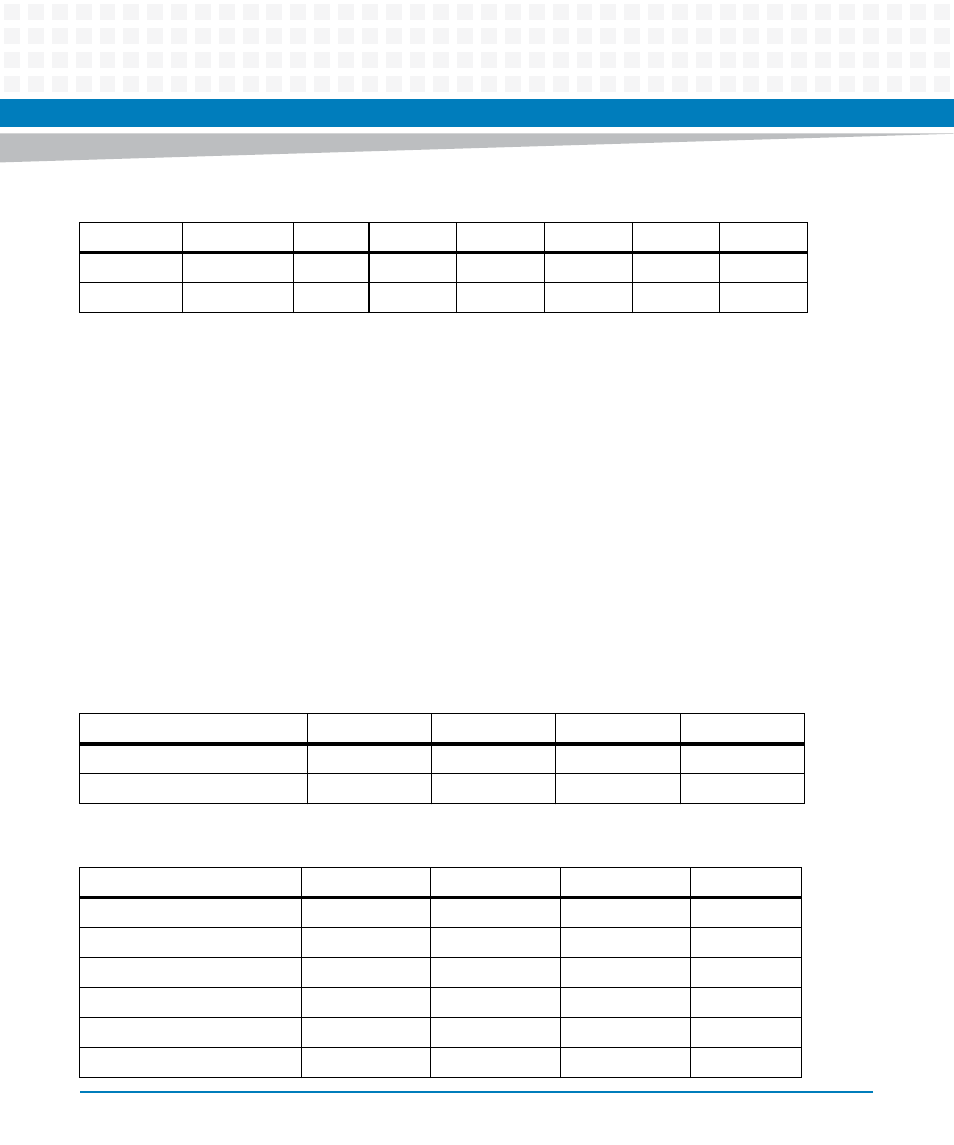
RTM SEEPROM Address Switch (S1)
A 4-position SMT configuration switch is located on the RTM to set the device address of the
RTM serial EEPROM device. The switch settings are defined in the following table.
20
0 01011
ON
ON
OFF
ON
OFF
OFF
21
1 01010
OFF
ON
OFF
ON
OFF
ON
Table 1-4 Slot Geographical Address Settings (continued)
Slot Address
GAP GA(4:0)
SW3
SW4
SW5
SW6
SW7
SW8
Table 1-5 RTM EEPROM Address Switch Assignments
Position
SW1
SW2
SW3
SW4
Function
A0
A1
A2
Not Used
OFF
1
1
1
Table 1-6 EEPROM Address Settings
Device Address
A(2:0)
SW1
SW2
SW3
$A0
000
ON
ON
ON
$A2
001
OFF
ON
ON
$A4
010
ON
OFF
ON
$A6
011
OFF
OFF
ON
$A8
100
ON
ON
OFF
$AA (Factory)
101
OFF
ON
OFF