14 mpc8540 real-time clock input, 15 mpc8540 lbc clock divisor, Mpc8540 real-time clock input – Artesyn MVME3100 Single Board Computer Installation and Use (June 2014) User Manual
Page 138: Mpc8540 lbc clock divisor, Programming details
Programming Details
MVME3100 Single Board Computer Installation and Use (6806800M28E)
138
7.14 MPC8540 Real-Time Clock Input
The MPC8540 real-time clock (RTC) input is driven by a 1 MHz clock generated by the control
and timers PLD. This provides a fixed clock reference for the RTC that software can use as a
known timing reference. To select this 1 MHz clock as the RTC timer reference, software must
set the SEL_TBCLK bit in the MPC8540 HID0 register.
7.15 MPC8540 LBC Clock Divisor
The MPC8540 LBC clock output is used by the control and timers PLD. The LBC clock is derived
from a divide by 2, 4 or 8 ratio of the internal CCB (core complex bus) clock as determined by
the clock ratio register (LCRR[CLKDIV]). For proper operation of the local bus, CLKDIV must be
set for divide by 8, which is the default value. The software must leave this register configured
for divide by 8 during initialization.
MPC9855
CLK66
25
Oscillator
2
3.3V
BCM5461S
CLK25_25V_PHY
25
Oscillator/
Buffer
2
2.5V
BCM5221
CLK25_33V_PHY
25
Oscillator/
Buffer
1
3.3V
Control and Timers
PLD
CLK25_33V_PLD
25
Oscillator/
Buffer
1
3.3V
CLK_LBC
CCB_CLK/8 (333
MHz/8)
MPC8540
1
3.3V
QUART
CLK_UART
1.8432
Oscillator
1
3.3V
sATA
CLK25
25
Oscillator
1
3.3V
USB
CLK48
48
Oscillator
1
3.3V
RTC
CLK32
32.768 kHz
Crystal
1
3.3V
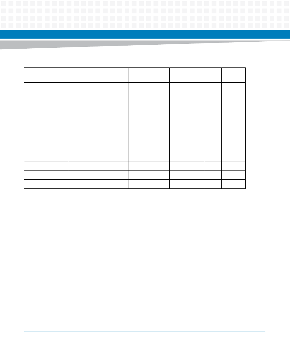
Table 7-10 Clock Assignments (continued)
Device
Clock Signal(s)
Frequency (MHz)
Clock Tree
Source
Qty
VIO