Table 1-7, Mvme3100 connectors, Table 1-8 – Artesyn MVME3100 Single Board Computer Installation and Use (June 2014) User Manual
Page 33: Mvme721 rear transition module connectors, Hardware preparation and installation
Hardware Preparation and Installation
MVME3100 Single Board Computer Installation and Use (6806800M28E)
33
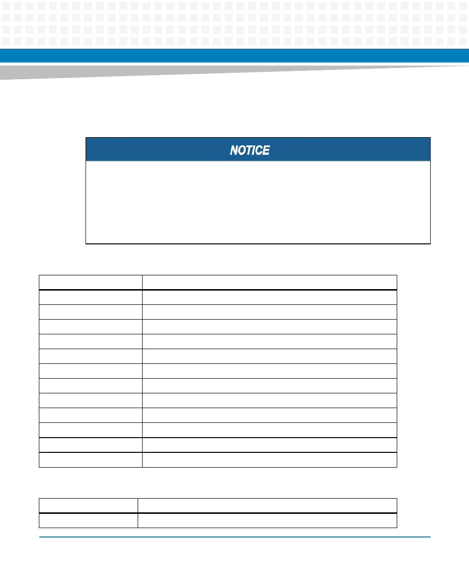
shows the locations of the various connectors while
list them for you. Refer to
for the pin assignments of the
connectors listed below.
Damage of the Product and Additional Devices and Modules
Incorrect installation or removal of additional devices or modules damages the product
or the additional devices or modules.
Before installing or removing additional devices or modules, read the respective
documentation and use appropriate tools.
Table 1-7 MVME3100 Connectors
Connector
Function
J4
PMC expansion connector
J11, J12, J13, J14
PCI mezzanine card (PMC) slot 1 connector
J21, J22, J23
PCI mezzanine card (PMC) slot 2 connector
J24
Boundary scan header
J25
COP header
J27
USB connector
J28
Front panel sATA connector
J29
Planar sATA connector
J30
Planar sATA power connector
J41B
10/100/1000Mb/s Ethernet connector
J41A
COM port connector
P1, P2
VME backplane connectors
Table 1-8 MVME721 Rear Transition Module Connectors
Connector
Function
J1A, J1B, J1C, J1D
COM port connectors