13 clock distribution, Table 7-10, Clock assignments – Artesyn MVME3100 Single Board Computer Installation and Use (June 2014) User Manual
Page 137: Clock distribution, Programming details
Programming Details
MVME3100 Single Board Computer Installation and Use (6806800M28E)
137
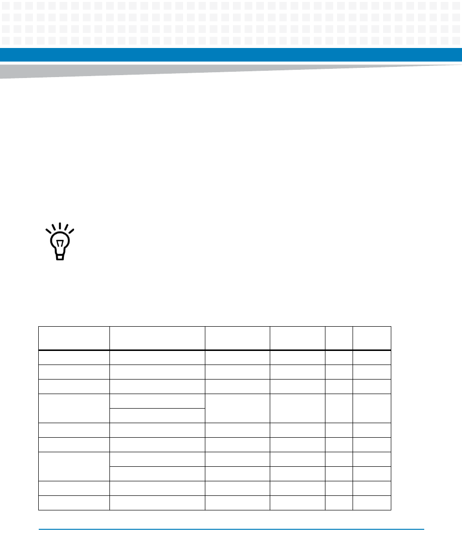
7.13 Clock Distribution
The clock function generates and distributes all of the clocks required for system operation.
The clock tree is designed in such a manner as to maintain the strict edge-to-edge jitter and low
clock-to-clock skew required by the devices. Additional clocks required by individual devices
are generated near the devices using individual oscillators.
lists the
clocks required on the MVME3100 along with their frequency and source. The clock tree A
frequencies on bus A have a default configuration of 66 MHz. The 33/66/100 MHz clocks are
dynamically configured at reset depending on the state of the PCIXCAP and M66EN pins on bus
B.
The PCI clock trees A, B, and C are not required to be synchronized with each other.
Table 7-10 Clock Assignments
Device
Clock Signal(s)
Frequency (MHz)
Clock Tree
Source
Qty
VIO
MPC8540
CLK_8540
66/100
A
1
3.3V
TSi148
CLK_VME
66/100
A
1
3.3V
sATA
CLK_SATA
66/100
A
1
3.3v
PCI6520 Primary
CLK_P2P_ABP
66/100
A
2
3.3V
CLK_P2P_ACP
PMC1
CLK_PMC1
33/66/100
B
1
3.3V
PMC2
CLK_PMC2
33/66/100
B
1
3.3V
PCI6520
Secondary
CLK_P2P_ABS
33/66/100
B
1
3.3V
CLK_P2P_ACS
33
C
1
3.3V
USB
CLK_USB
33
C
1
3.3V
PMCspan
CLK_SPAN
33
C
1
3.3V