2 control registers, Table 6-18, Tick timer control registers – Artesyn MVME3100 Single Board Computer Installation and Use (June 2014) User Manual
Page 120
Memory Maps
MVME3100 Single Board Computer Installation and Use (6806800M28E)
120
Prescalar Adjust: The prescaler adjust value is determined by the following formula:
Prescaler adjust = 256 - (CLKIN/CLKOUT) where CLKIN is the input clock source in MHz and
CLKOUT is the desired output clock reference in MHz.
6.1.16.2 Control Registers
The prescaler provides the clock required by each of the four timers. The tick timers require a
1 MHz clock input. The input clock to the prescaler is 25 MHz. The default value is set for $E7,
which gives a 1 MHz reference clock for a 25 MHz input clock source.
ENC: Enable counter. When this bit is high, the counter increments. When this bit is low, the
counter does not increment.
COC: Clear counter on compare. When this bit is high, the counter is reset to 0 when it
compares with the compare register. When this bit is low, the counter is not reset.
COVF: Clear overflow bits. The overflow counter is cleared when a 1 is written to this bit.
OVF: Overflow bits. These bits are the output of the overflow counter. The overflow counter is
incremented each time the tick timer sends an interrupt to the local bus interrupter. The
overflow counter can be cleared by writing a 1 to the COVF bit.
ENINT: Enable interrupt. When this bit is high, the interrupt is enabled. When this bit is low, the
interrupt is not enabled.
CINT: Clear interrupt.
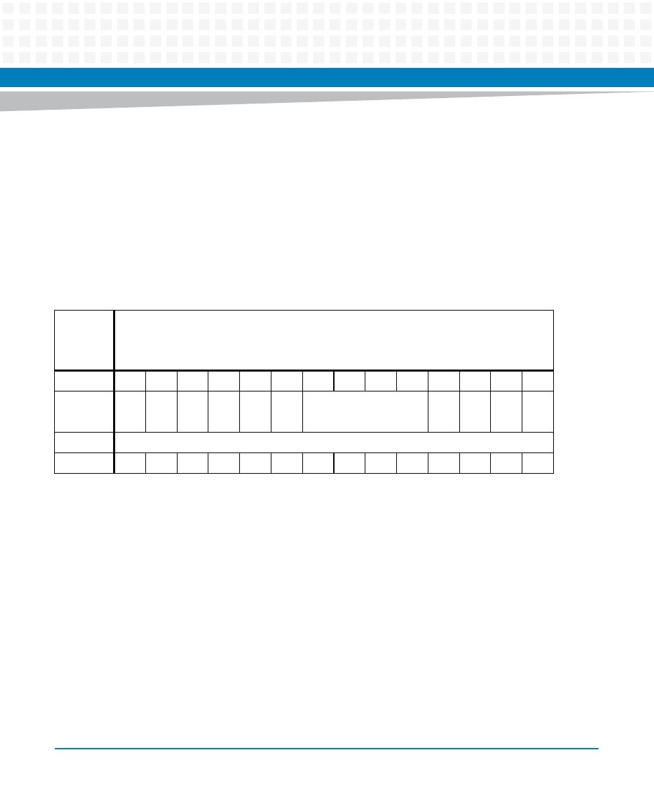
Table 6-18 Tick Timer Control Registers
REG
Tick Timer 1 Control Register - 0xE2020010 (32 bits)
Tick Timer 2 Control Register - 0xE2020020 (32 bits)
Tick Timer 3 Control Register - 0xE2020030 (32 bits)
Tick Timer 4 Control Register - 0xE2020040 (32 bits)
BIT
31
...
11
10
9
8
7
6
5
4
3
2
1
0
FIELD
RS
V
D
...
RS
V
D
INT
S
CINT
ENINT
OV
F
RS
V
D
COV
F
CO
C
ENC
OPER
R/W
RESET
0
...
0
0
0
0
0
0
0
0
0
0
0
0