2 mpc8540 reset configuration, Table 7-1, Mpc8540 power-on reset configuration settings – Artesyn MVME3100 Single Board Computer Installation and Use (June 2014) User Manual
Page 124: Mpc8540 reset configuration, Programming details
Programming Details
MVME3100 Single Board Computer Installation and Use (6806800M28E)
124
7.2
MPC8540 Reset Configuration
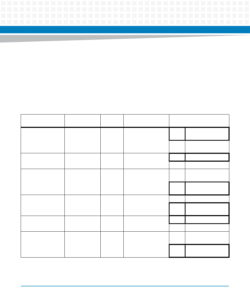
The MVME3100 supports the power-on reset (POR) pin sampling method for MPC8540 reset
configuration. The states of the various configuration pins on the MPC8540 are sampled when
reset is de-asserted to determine the desired operating modes. The following table describes
the configuration options and the corresponding default setting. Refer to the MPC8540
Reference Manual listed in
Appendix B, Related Documentation
, for additional details and/or
programming information.
Table 7-1 MPC8540 Power-on Reset Configuration Settings
MPC8540 Signal
Select Option
Default
Setting
Description
State of Bit vs Function
1
PCI_REQ64_L
PLD logic
0
PCI-32 Configuration
0
PCI/PCI-X interface is
64-bit
1
PCI/PCI-X interface is
32-bit
PCI_GNT1_L
Resistor
0
PCI Interface I/O
Impedance
0
25 ohm drivers
1
42 ohm drivers
PCI_GNT2_L
Resistor
1
PCI Arbiter
Configuration
0
Disabled on-chip
PCI/PCI-X arbiter
2
1
Enabled on-chip
PCI/PCI-X arbiter
PCI_GNT3_L
Resistor
1
PCI Debug
Configuration
0
PCI debug enabled
1
PCI operates in
normal mode
PCI_GNT4_L
Switch
0
PCI/PCI-X
Configuration
0
PCI-X mode
1
PCI mode
EC_MDC
Resistor
1
TSEC Width
Configuration
0
Ethernet in reduced
mode (RTBI or RGMII)
1
Ethernet in standard
mode (TBI or GMII)