10 sata connectors (j28 and j29), 3 headers, 1 boundary scan header (j24) – Artesyn MVME3100 Single Board Computer Installation and Use (June 2014) User Manual
Page 103: Table 5-16, Sata connectors (j28 and j29) pin assignments, Table 5-17, Boundary scan header (j24) pin assignments, Sata connectors (j28 and j29), Boundary scan header (j24), Pin assignments
Pin Assignments
MVME3100 Single Board Computer Installation and Use (6806800M28E)
103
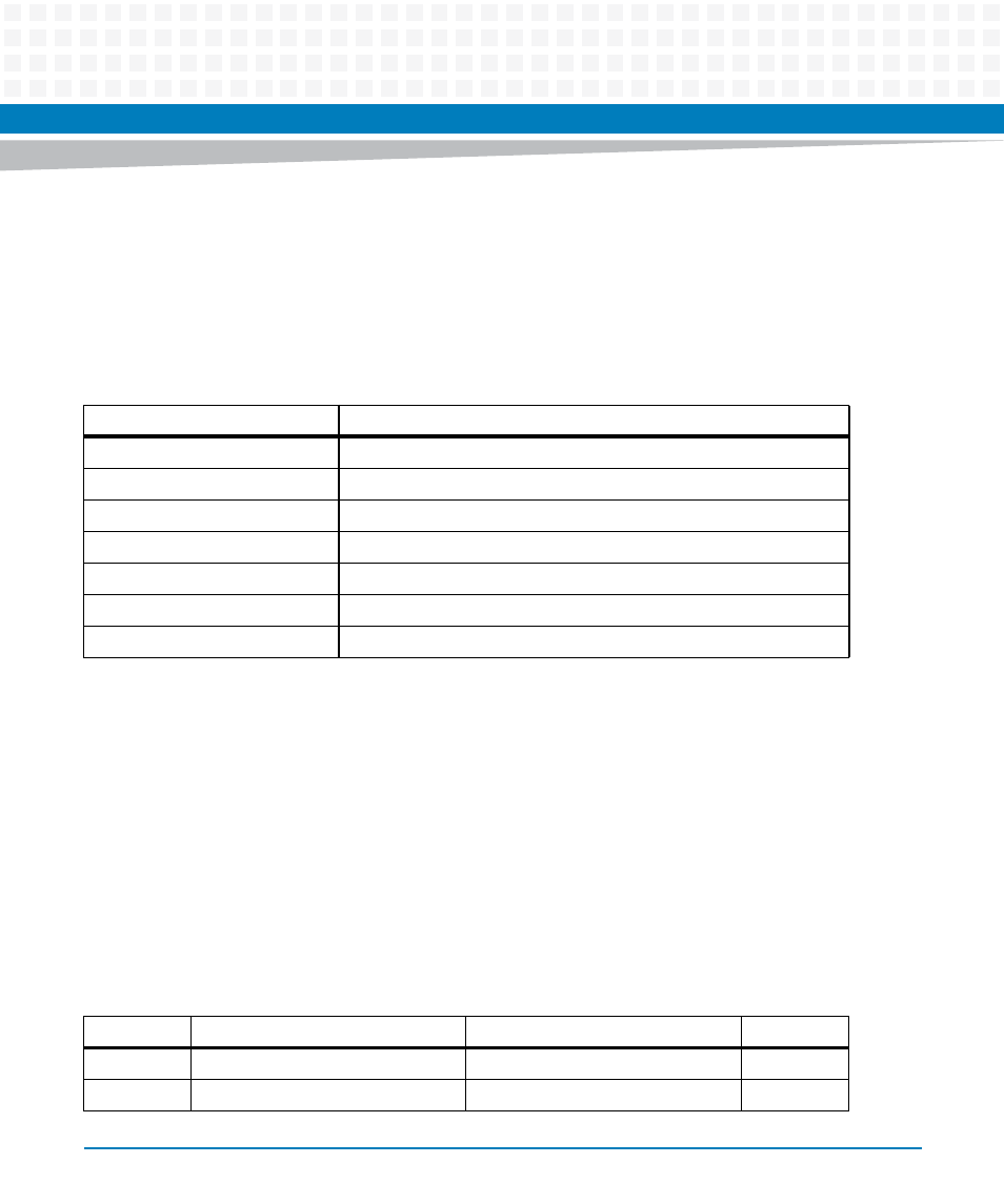
5.2.10 sATA Connectors (J28 and J29)
The MVME3100 has two sATA connectors. J28 is an internal type sATA connector located on the
planar and is intended to connect to a drive located on the board or somewhere inside the
chassis. J29 is an external type sATA connected located on the front panel and is intended to
connect to an external sATA drive. The pin assignment for these connectors is as follows:
5.3
Headers
This section describes the pin assignments of the Headers on the MVME3100. For Hheader
settings, refer to
5.3.1
Boundary Scan Header (J24)
The 14-pin boundary scan header provides an interface for programming the on-board PLDs
and for boundary scan testing/debug purposes. The pin assignments for this header are as
follows:
Table 5-16 sATA Connectors (J28 and J29) Pin Assignments
Pin
Signal
1
GND
2
SATA_TX+
3
SATA_TX-
4
GND
5
SATA_RX-
6
SATA_RX+
7
GND
Table 5-17 Boundary Scan Header (J24) Pin Assignments
Pin
Signal
Signal
Pin
1
TRST_L
GND 2
3
TDO
GND 4