Table 5-13, Mvme721 host i/o connector (j10) pin assignments, Mvme721 pmc i/o module (pim) connectors (j10, j14) – Artesyn MVME3100 Single Board Computer Installation and Use (June 2014) User Manual
Page 100: Pin assignments
Pin Assignments
MVME3100 Single Board Computer Installation and Use (6806800M28E)
100
5.2.7
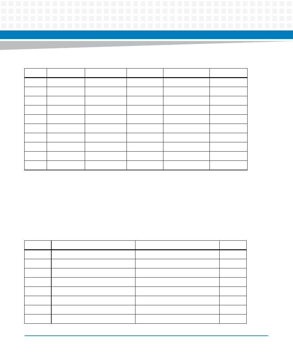
MVME721 PMC I/O Module (PIM) Connectors (J10, J14)
PMC Host I/O connector J10 routes only power and ground from VME P2. There are no Host I/O
signals on this connector. The MVME3100 routes PMC I/O from J14 of PMC Slot 1 to VME P2
rows A and C. The MVME721 routes these signals (pin-for-pin) from VME P2 to PMC I/O Module
connector J14. See
and
for the pin assignments.
23
SP3RTS
PMC1_IO46
VD24
PMC1_IO45
E2-3-
24
GND
PMC1_IO48
VD25
PMC1_IO47
E2-3+
25
SP4RX
PMC1_IO50
VD26
PMC1_IO49
GND
26
GND
PMC1_IO52
VD27
PMC1_IO51
E2-2-
27
SP4TX
PMC1_IO54
VD28
PMC1_IO53
E2-2+
28
GND
PMC1_IO56
VD29
PMC1_IO55
GND
29
SP4CTS
PMC1_IO58
VD30
PMC1_IO57
E2-1-
30
GND
PMC1_IO60
VD31
PMC1_IO59
E2-1+
31
SP4RTS
PMC1_IO62
GND
PMC1_IO61
GND
32
GND
PMC1_IO64
+5V
PMC1_IO63
+5V
Table 5-12 VME P2 Connector Pinouts (continued)
Pin
P2-Z
P2-A
P2-B
P2-C
P2-D
Table 5-13 MVME721 Host I/O Connector (J10) Pin Assignments
Pin
Signal
Signal
Pin
1
No Connect
No Connect
2
3
No Connect
No Connect
4
5
+5V
No Connect
6
7
No Connect
No Connect
8
9
No Connect
+3.3V
10
11
No Connect
No Connect
12
13
GND
No Connect
14
15
No Connect
No Connect
16