5 two-wire serial interface, Table 7-4, I2c bus device addressing – Artesyn MVME3100 Single Board Computer Installation and Use (June 2014) User Manual
Page 131: Two-wire serial interface, Programming details
Programming Details
MVME3100 Single Board Computer Installation and Use (6806800M28E)
131
7.5
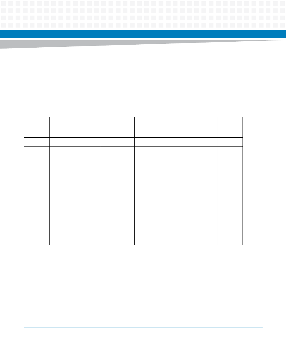
Two-Wire Serial Interface
A two-wire serial interface for the MVME3100 is provided by an I
2
C compatible serial controller
integrated into the MPC8540. The MPC8540 I
2
C controller is used by the system software to
read the contents of the various I
2
C devices located on the MVME3100. The following table
contains the I
2
C devices used for the MVME3100 and their assigned device addresses.
Table 7-4 I2C Bus Device Addressing
I2C Bus
Address
Device Address
A2 A1 A0
(binary)
Size (bytes)
Device Function
Notes
$90
000
N/A
DS1621 temperature sensor
$A0
000
256 x 8
DDR memory SPD (SODIMM module
banks 1 and 2 corresponding to
MPC8540 memory controller chip
selects 0 and 1)
1
$A2
001
Reserved
$A4
010
65,536 x 8
User configuration
2
$A6
011
65,536 x 8
User configuration
2
$A8
100
8192 x 8
VPD (on-board system configuration)
2
$AA
101
8192 x 8
RTM VPD (off-board configuration)
2
,
3
$AC
110
Reserved
$AE
111
Reserved
$D0
N/A
N/A
DS1375 real-time clock
1. Each SPD defines the physical attributes of each bank or group of banks. If both banks of a SODIMM are populated they
are the same speed and memory size.
2. This is a dual address serial EEPROM.
3. The device address is user selectable using switches on the RTM. The recommended address setting for the MVME3100
is $AA.