Table 2-2, Mvme721 led status indicators, Table 2-3 – Artesyn MVME3100 Single Board Computer Installation and Use (June 2014) User Manual
Page 38: Additional onboard status indicators, Startup and operation
Startup and Operation
MVME3100 Single Board Computer Installation and Use (6806800M28E)
38
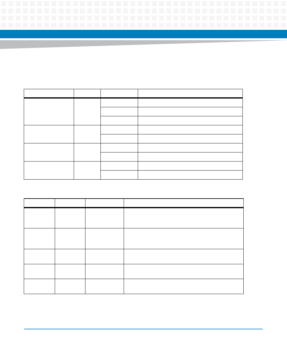
The MVME721 rear transition module also has four status indicators. The following table
describes these indicators:
Table 2-2 MVME721 LED Status Indicators
Function
Label
Color
Description
GENET 2 Link/Speed
SPEED
Off
No link
Yellow
10/100Base-T operation
Green
1000Base-T operation
GENET 2 Activity
ACT
Blinking Green
Activity proportional to bandwidth utilization.
Off
No activity
ENET 1 Link/Speed
SPEED
Off
No link
Yellow
10/100Base-T operation
ENET 1 Activity
ACT
Blinking Green
Activity proportional to bandwidth utilization.
Off
No activity
Table 2-3 Additional Onboard Status Indicators
Function
Label
Color
Description
User
Defined LED
2
DS7
(silkscreen)
Green
This indicator is illuminated by software assertion of its
corresponding register bit.
User
Defined LED
3
DS8
(silkscreen)
Green
This indicator is illuminated by software assertion of its
corresponding register bit.
Power
Supply Fail
DS1
(silkscreen)
Red
This indicator is illuminated to indicate a power supply
fail condition.
sATA 0
Activity
DS4
(silkscreen)
Green
sATA 0 activity indicator
sATA 1
Activity
DS5
(silkscreen)
Green
sATA 1 activity indicator