7 system indicator register, Table 6-6, System indicator register – Artesyn MVME3100 Single Board Computer Installation and Use (June 2014) User Manual
Page 111
Memory Maps
MVME3100 Single Board Computer Installation and Use (6806800M28E)
111
6.1.7
System Indicator Register
The MVME3100 board provides a System Indicator register that may be read by the system
software to determine the state of the on-board status indicator LEDs or written to by system
software to illuminate the corresponding on-board LEDs.
BRD_FAIL: Board fail. This bit controls the board fail LED located on the front panel. A set
condition illuminates the front-panel LED and a cleared condition extinguishes the front-panel
LED.
USR1_LED: User LED 1. This bit controls the USR1 LED located on the front panel. A set
condition illuminates the front-panel LED and a cleared condition extinguishes the front-panel
LED.
USR2_LED: User LED 2. This bit controls the planar USR2 LED. A set condition illuminates the
LED and a cleared condition extinguishes the LED.
USR3_LED: User LED 3. This bit controls the planar USR3 LED. A set condition illuminates the
LED and a cleared condition extinguishes the LED.
RSVD: Reserved for future implementation.
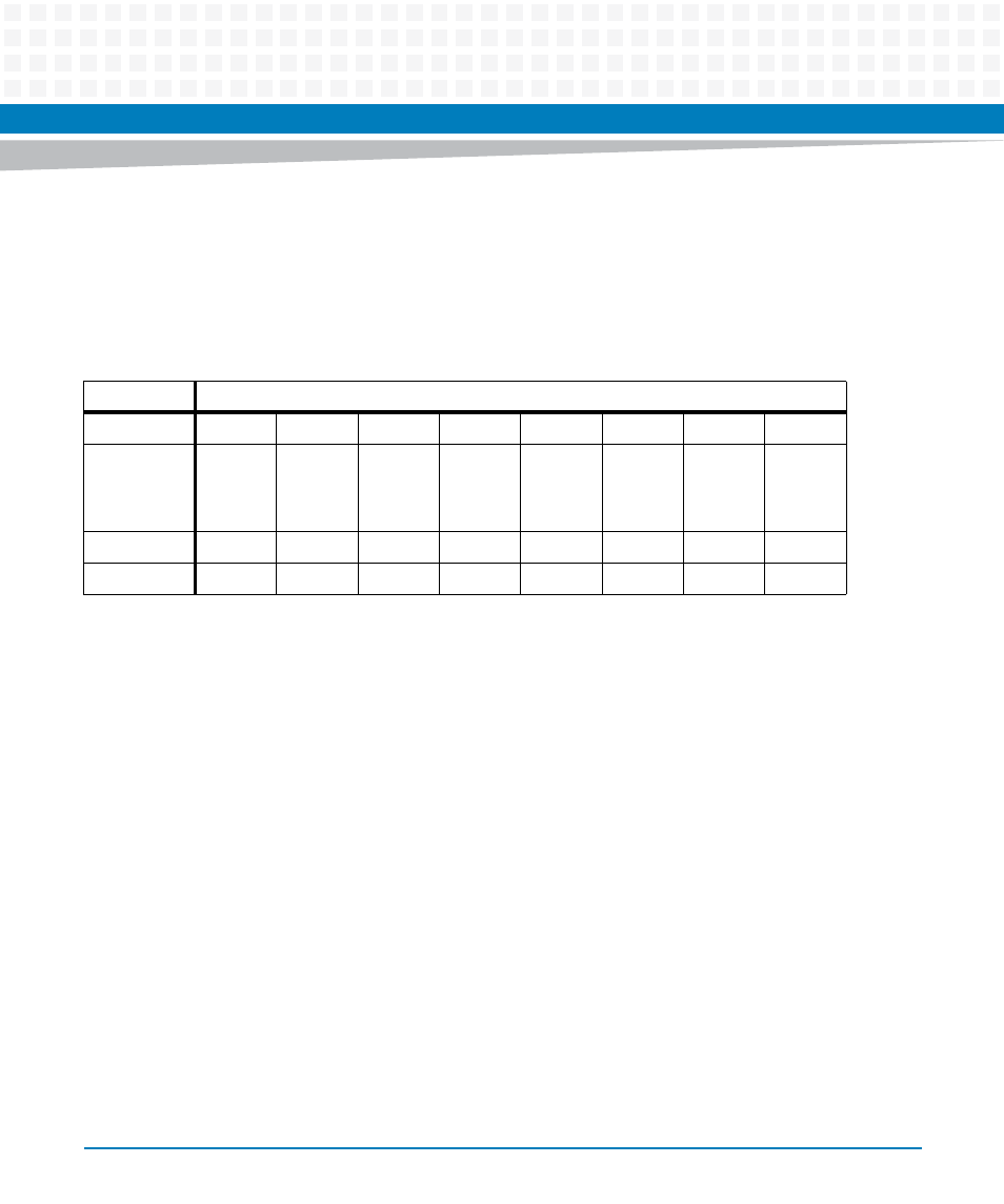
Table 6-6 System Indicator Register
REG
System Indicator Register - 0xE2000002
BIT
7
6
5
4
3
2
1
0
FIELD
RS
V
D
RS
V
D
RS
V
D
RS
V
D
U
SR3
U
SR2
U
SR1
BRD_F
AIL
OPER
R
R
R
R
R/W
R/W
R/W
R/W
RESET
0
0
0
0
0
0
0
1