2 shuttle knobs, 3 buttons – AMETEK 2001RP User Manual
Page 39
User and Programming Manual - Rev R
2001RP
29
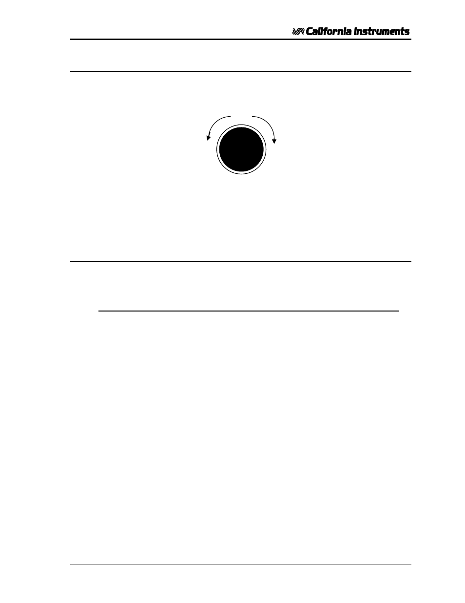
4.1.2 Shuttle knobs
Counter
Clockwise
clockwise
DECREASE
INCREASE
Figure 4-3: Shuttle Knob
There are two shuttle knobs located below the LCD display which are used to change setup
parameters for voltage, frequency and current limit. The SELECT button selects the function
of the right shuttle. The right shuttle will control either the frequency or the current limit as
indicated by the indicator above the right LCD. The left shuttle always controls the voltage.
4.1.3 Buttons
There are three function buttons for the Output Voltage Range, Output State and Shuttle
Mode. The following is a description of these buttons:
RANGE
The RANGE button is used to change the voltage range
between the low range (0 to 150, 135 or 115 volts) and high
range (0 to 300, 270 or 230 volts). The LED above the
switch will light to indicate the high voltage range selection.
The output voltage will be reset to zero voltage after a range
change. If the 2001RP-AV is configured for a single
voltage range, this button is disabled.
The same button may be used to put the 2001RP in the
AUTO voltage range change mode. This button toggles
from Lo, Auto, Hi and back to Lo. The AUTO LED will
illuminate when the AUTO range mode is enabled. While in
AUTO mode, the 2001RP will switch to the high range
whenever a value larger than the low range limit is
programmed. Whenever a value below the low range limit is
programmed, the unit will switch to the low voltage range.
The output is momentarily interrupted when a range change
occurs.
To take the unit out of AUTO mode, press the RANGE
button again.
KEY
DESCRIPTION
OUTPUT
The OUTPUT button will toggle the output relay to connect
or disconnect the output. The LED above the button will
light when the output relay is closed. No output voltage will
be present when the OUTPUT button is off despite the level
of voltage programmed.