4 mechanical installation, 5 input wiring – AMETEK 2001RP User Manual
Page 29
User and Programming Manual - Rev R
2001RP
19
3.4 Mechanical Installation
The power source has been designed for rack mounting in a standard 19 inch rack. The unit
must be supported from the sides with optional rack slides. See Accessory Equipment/Rack
Slides in Section 1.2. The cooling fan at the rear of the unit must be free of any obstructions
which would interfere with the flow of air. A 2.5 inch (6.35cm) clearance should be
maintained between the rear of the unit and the rear panel of the mounting cabinet. Keep in
mind that adequate ventilation of the mounting cabinet must be maintained for sufficient
cooling of the power source. Use louvered side panels, and/or perforated rear panels to
assure adequate airflow. Also, the air intake holes on the sides of the power source must not
be obstructed when mounted inside cabinet. See Figure 3-1.
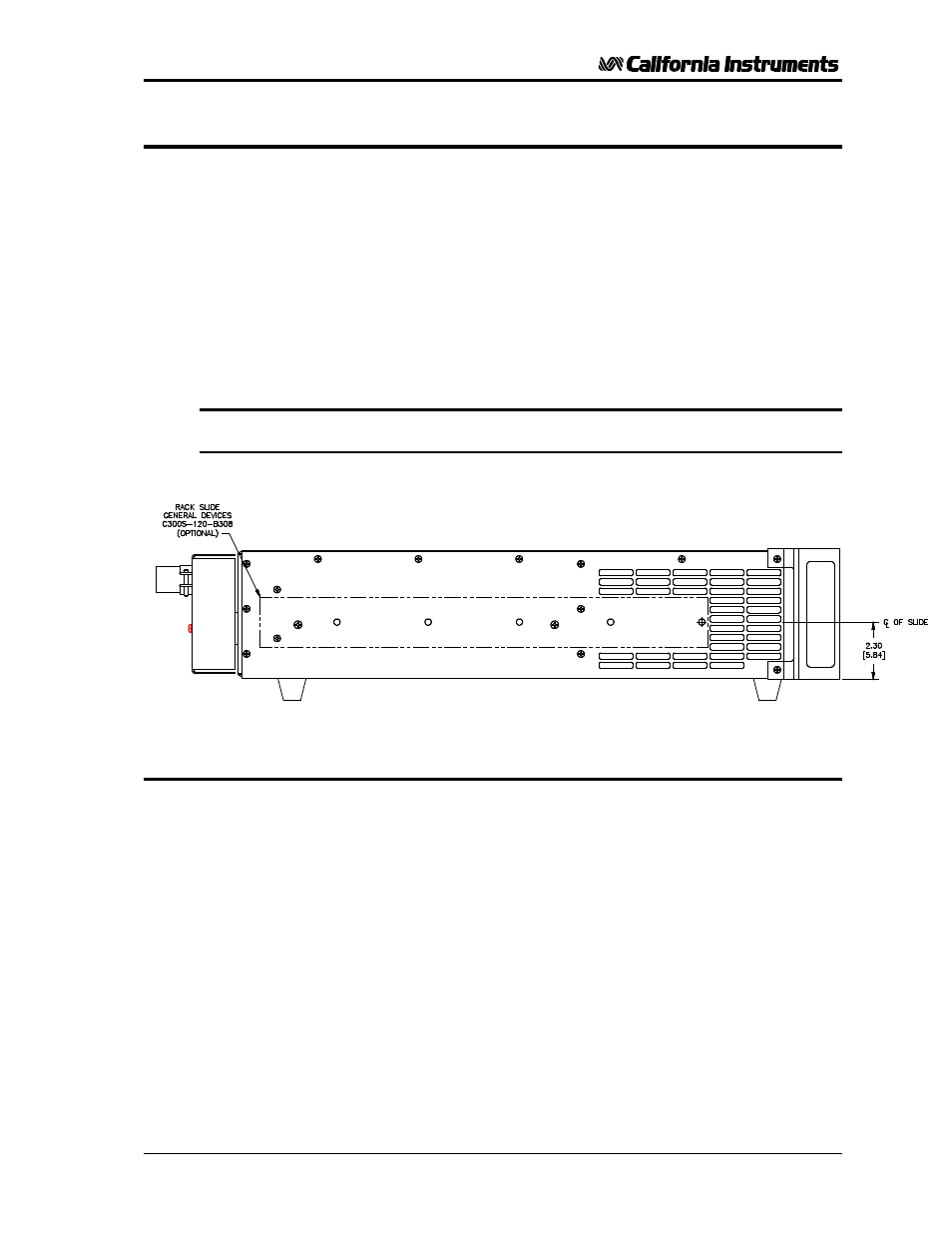
The rack mount slide mounting holes centerlines on the side of the power source are 2.30
inches / 58.4 mm above the bottom edge of the front panel.
Note:
The 2001RP series models cannot be mounted in a cabinet by just
using the front panel rack ears. They require additional support.
Figure 3-5: Rack Mount Slides (-RMS option) position
3.5 Input Wiring
The AC Power Source must be operated from a three-wire single-phase service. The mains
source must have a current rating greater than or equal to 35 A for the low input range. Use
the supplied safety cover/strain relief when connecting the input wires to the power source.
Refer to Figure 3-2 and Figure 3-6for the input power connections.
Also loop the input ground wire through the supplied ferrite filter (Ci P/N 250508) core 5 times
(5 turns) for 230V input models (AWG#12) or 3 turns for 115V input models (AWG#10).
Enclose ferrite core with the safety cover or leave it outside the safety cover if insufficient
space is available.
When connecting the input wires to input terminal block, make sure the safety grounding wire
from the strain relief grommet including the 5 turns around the ferrite core is longer than the
Line and Neutral wire so that the ground wire will be the last one to take any strain. For low-
range input operation (115V) we recommend #10 AWG input wires as a minimum. For high-
range input operation (230V) #12AWG is recommended. For European applications (230V),
the following input cord set may also be used:
Panel Components # 86518030 Rated 16A, 250V, 70
° C, 3x 1.5mm² conductor size. VDE
approved. Install as described above for discreet wiring.