6 output connections – AMETEK 2001RP User Manual
Page 30
User and Programming Manual - Rev R
20
2001RP
3.6 Output Connections
The output terminal block is located at the rear of the power source. All load connections
must be made on the rear panel terminal block. The remote sense inputs are normally
jumpered directly to the adjacent power output pins on the output connector. If the sense
terminals are not connected to the power output pins, the output voltage may rise significantly
above the programmed value. When connecting the output wires, use the supplied safety
cover/strain relief and mount over the output connector. Also mount the supplied snap-on
ferrite filter around the output wiring between the output terminals and the strain relief
grommet. Enclose ferrite filter with the safety cover. See Figure 3-6.
If the load is a significant distance from the output terminal strip it may be desirable to sense
the output voltage directly at the load. If remote sensing is to be used, then the size of the
output power wiring must be heavy enough to prevent a voltage difference greater than 7% of
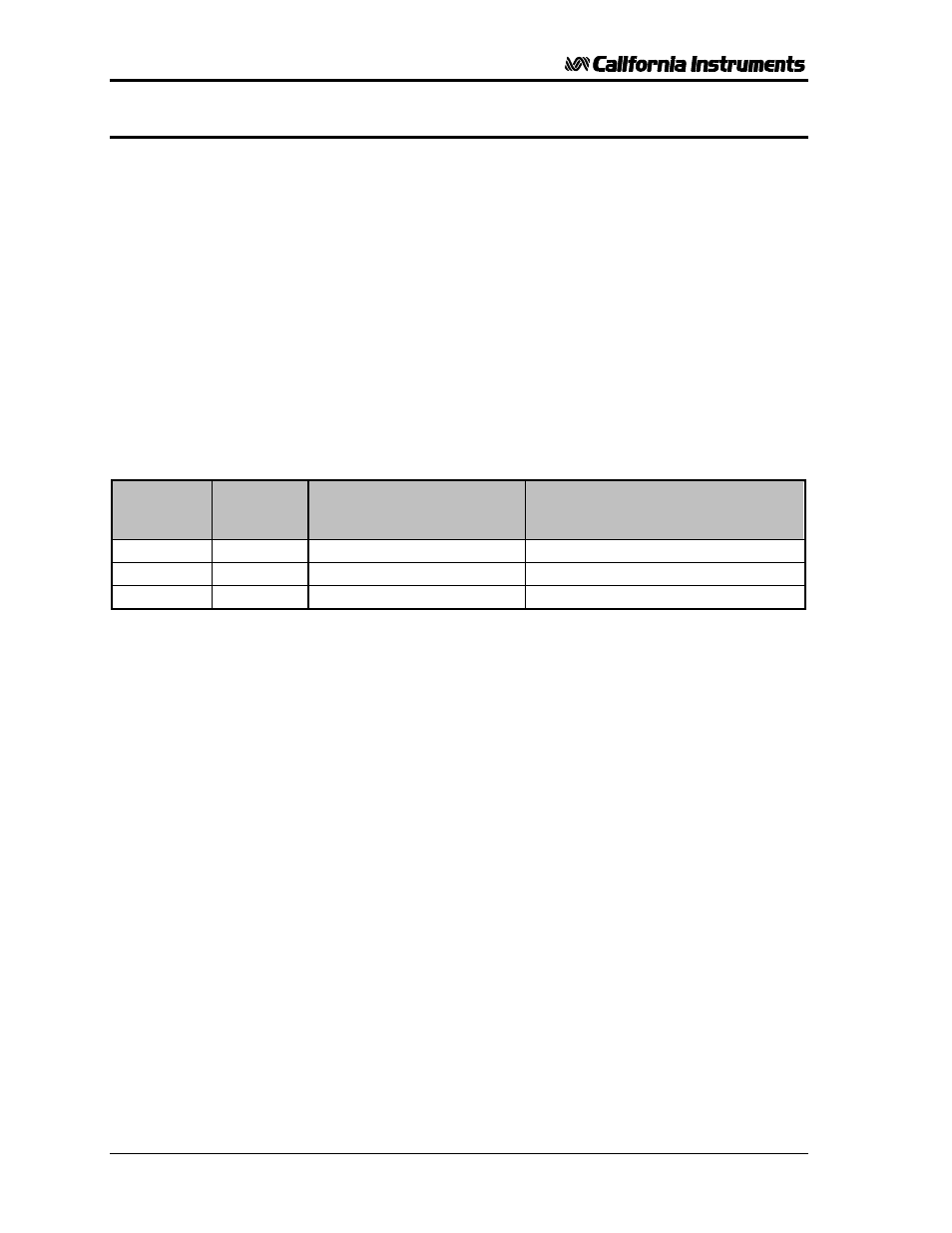
the programmed value from the power output pins to the sense input pins. Table 3-1 shows
the maximum length of the output wires. The table assumes the Remote Sense input is
connected at the load. For 2001RP models with lower voltage ranges than 150 V
RMS
, the
wire gauge may have to be reduced. Numbers shown in Table 3-1 are for standard 2001RP
model with 150 V
RMS
range.
Maximum
output current
Wire gauge
(AWG)
Conductor nom. diameter
Inches mm
Maximum wire length between output
terminals and load
feet meter
13.4 A
RMS
14
.072 inch 1.93 mm
46 ft. 14 m.
13.4 A
RMS
12
.090 inch 2.27 mm
73 ft. 22 m.
13.4 A
RMS
10
.112 inch 2.84 mm
117ft. 35 m.
Table 3-1: Maximum Output Wiring Lengths
The Remote Sense inputs must be connected or an output voltage 7% higher than the
programmed output will be generated. If the 2001RP is configured for constant voltage, a
fault will be generated.