CIRCUTOR CVM-C10 Series User Manual
Page 68
4�10�3�6�2�
Neutral current transformation ratios (CVM-C10-ITF-IN)�
Table 24:Modbus memory map: Neutral current transformation ratios�
Transformation ratios
Configuration variable
(1)
Address
Valid data margin
Default
value
Neutral current primary
271A
1 - 10000
5
Neutral current secondary
271B
1: .../1A
5: ../5 A
5
(1)
All variables must be programmed at the same time.
4�10�3�6�3�
Number of quadrants
Table 25:Modbus memory map: Number of quadrants
Maximum demand
Configuration variable
Address
Valid data margin
Default
value
Number of quadrants
2B64
0: 4 quadrants
1: 2 quadrants
0
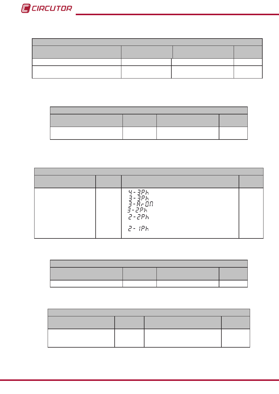
4�10�3�6�4�
Type of installation
Table 26:Modbus memory map: Type of installation
Type of installation
Configuration variable
Address
Valid data margin
Default
value
Type of installation
2B5C
0:
Three-phase network with 4 wires�
1:
Three-phase network with 3 wires.
2:
Three-phase network with 3 wires, Aron.
3:
Two-phase network with 3 wires.
4:
Single-phase network with 2 wires, phase-
to-phase.
5:
Single-phase network with 2 wires, phase-
to-neutral.
0
4�10�3�6�5� Maximum demand
Table 27:Modbus memory map: Maximum demand
Maximum demand
Configuration variable
Address
Valid data margin
Default
value
Integration period
274C
1 - 60 minutes
15
4�10�3�6�6� Operating profile
Table 28:Modbus memory map: Operating profile
Operating profile
Configuration variable
Address
Valid data margin
Default
value
Operating profile
2B60
0: Analyzer
1: User
2: Electrical energy efficiency, e
3
0
68
CVM-C10
Instruction Manual