CIRCUTOR CVM-C10 Series User Manual
Page 49
If you press the
key after changing the last digit, it will jump back to the first digit so you
can modify the previously programmed values again.
To validate the data, press
for 3 seconds and the
prog icon will disappear from the display.
Press key
to access the next programming step.
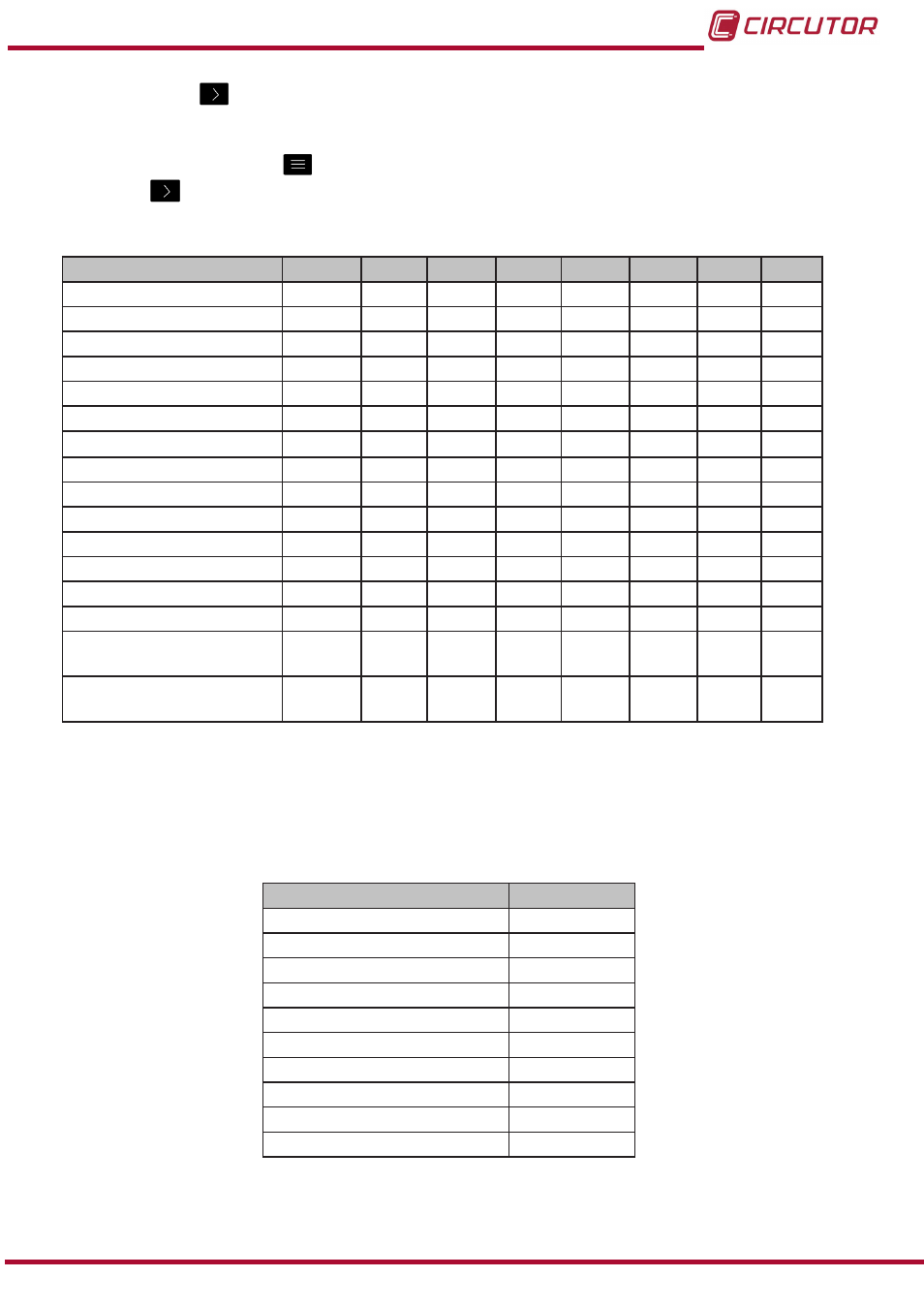
Table 12: Parameter codes used to program the outputs�
Parameter
Phase
Code Phase Code Phase Code
Phase Code
Phase-Neutral Voltage
L1
01
L2
09
L3
17
-
-
Current
L1
02
L2
10
L3
18
-
-
Active power
L1
03
L2
11
L3
19
III
25
Inductive Reactive Power
L1
04
L2
12
L3
20
III
26
Capacitive Reactive Power
L1
05
L2
13
L3
21
III
27
Apparent power
L1
06
L2
14
L3
22
III
28
Power factor
L1
07
L2
15
L3
23
III
29
Cosine φ
L1
08
L2
16
L3
24
III
30
% THD V
L1
36
L2
37
L3
38
-
-
% THD A
L1
39
L2
40
L3
41
-
-
Phase-Phase Voltage
L1/2
32
L2/3
33
L3/1
34
-
-
Frequency
-
31
-
-
-
-
-
-
Neutral current
-
35
-
-
-
-
-
-
Maximum current demand
L1
45
L2
46
L3
47
III
44
Active Power Maximum
Demand
-
-
-
-
-
-
III
42
Apparent Power Maximum
Demand
-
-
-
-
-
-
III
43
In addition, there are some parameters (
) that refer to the three phases at the same
time (OR function). If you have selected one of these variables, the alarm will be activated when
any of the three phases meets the programmed conditions.
Table 13:Multiple parameter codes for alarm programming�
Types of parameters
Code
Phase-Neutral Voltage
200
Current
201
Active power
202
Inductive Reactive Power
203
Capacitive Reactive Power
204
Power factor
205
Phase-Phase Voltage
206
% THD V
207
% THD A
208
Apparent Power
209
49
Instruction Manual
CVM-C10