Connection diagram, Cvm-c10-mv model, Cvm-c10 instruction manual – CIRCUTOR CVM-C10 Series User Manual
Page 12: Power supply v, Nl1 l2 l3 n
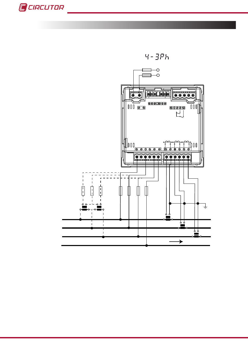
3.4.- CONNECTION DIAGRAM
3�4�1�- Measuring Three-Phase Networks with a 4-wire connection, CVM-C10-ITF and
CVM-C10-mV model�
Measurement system:
Power
Supply
V
L1
V
L2
V
L3
N
L1
L2
L3
N
POWER SUPPLY
INPUTS
A
(+) B(-)
GND
RS485
S1
S2
S1
S2 S1
S2
L1
P1
P2
L2
L3
300V ~
Ph-N
Ph-Ph
520V ~
N
V
L3
L2
V
L1
V
P1
P2 P1
P2
I1 I2
OUTPUTS
Rc R2 R1
Tc T2 T1
S0- S0+ S0+
V
L1
V
L2
V
L3
a
b
A
B
a
b
A
B
S1
S2
P1
P2
S1
S2
P1
P2
S1
S2
P1
P2
LOAD
Figure 3: Three-Phase measuring with a 4-wire connection, CVM-C10-ITF and CVM-C10-mV model�
12
CVM-C10
Instruction Manual
See also other documents in the category CIRCUTOR Measuring instruments:
- CVMk2 Series (152 pages)
- QNA500 series (111 pages)
- Wi-beee Series (32 pages)
- CVM-C5 Series (40 pages)
- CVM-MINI Series (26 pages)
- CVM-NET Series (2 pages)
- CVM-NET4 (7 pages)
- CVM-1D Series (2 pages)
- CVM-BDM Series (32 pages)
- PowerNet Series (2 pages)
- CVM-NRG96 Series (Available until stocks) (38 pages)
- CVM-B Series (320 pages)
- CVM96 Series (44 pages)
- CVM144 Series (58 pages)
- RS2RS (2 pages)
- TCP1RS+ (2 pages)
- EDS Series (5 pages)
- CMBUS series (24 pages)
- EDS-3G Series (6 pages)
- MDC-4 (30 pages)
- LM50-TCP+ (2 pages)
- MDC-20 (58 pages)
- ReadWatt Series (22 pages)
- CIRLAMP Series (102 pages)
- PowerStudio Series (42 pages)
- PowerStudio Series (110 pages)
- PowerStudio Series (110 pages)
- PowerStudio Series (292 pages)
- OPC Server PS/PSS (22 pages)
- SQL Data Export (28 pages)
- AR6 Series (69 pages)
- AR5L Series (52 pages)
- CIRe3 Series (50 pages)
- CIReQ (36 pages)
- QNA-P Series (36 pages)
- T3V Series (8 pages)
- CPM (Available until stocks) (20 pages)
- DHB Series (58 pages)
- DHB Series (46 pages)
- DHB Series (54 pages)
- DHB Series (50 pages)
- EMF-EMB Series (11 pages)
- SYNCHROMAX Series (2 pages)
- SYNCHROMAX Series (2 pages)