Altera Arria 10 Avalon-MM DMA User Manual
Page 92
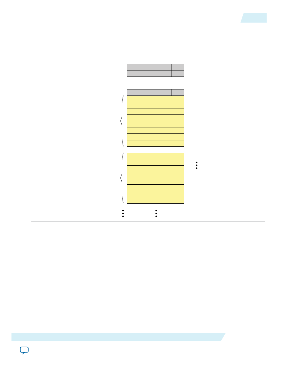
Figure 6-11: Descriptor Table Format
Assume the descriptor table includes 128 entries. The status table precedes a variable number of
descriptors in memory. The Read and Write Status and Descriptor Tables are at the address specified in
the
RC Read Descriptor Base Register
and
RC Write Descriptor Base Register
, respectively.
Reserved
Done 0xF000_0000
0xF000_0200
0xF000_0204
0xF000_0208
0xF000_020C
0xF000_0210
Reserved
Done
Reserved
Addresss
Done
SRC_ADDR_LOW
DESCRIPTOR_ID + DMA_LENGTH
SRC_ADDR_HIGH
DEST_ADDR_LOW
DEST_ADDR_HIGH
Descriptor 0
Descriptor 1
Descriptor 0 Status
Descriptor 1 Status
Descriptor 127 Status
127
0
Bits
RESERVED
RESERVED
RESERVED
1. Calculate the memory allocation required:
a. Each descriptor is 32 bytes. The three descriptors require 96 bytes of memory
b. Each entry in the status table is 4 bytes. The 128 entries require 512 bytes of memory.
The total memory allocation for the status and descriptor tables is 608 bytes.
2. Allocate 608 bytes of memory.
Assume that the start address of the allocated memory is 0xF000_0000.
3. Create the descriptor table in the PCI Express address space. Because the status table is stored before
the descriptors, the first descriptor is stored at 0xF000_0000 + 0x200 = 0xF000_0200.
a. Program 0x1000_0000 to source address 0xF000_02004.
This is the upper 32 bits of the source address.
b. Program 0x0000_0000 to source address 0xF000_0200.
This is the lower 32 bits of the source address.
c. Program 0x5000_0000 to destination address 0xF000_020C.
UG-01145_avmm_dma
2015.05.14
Read DMA Example
6-23
Registers
Altera Corporation