Altera SCFIFO User Manual
Page 23
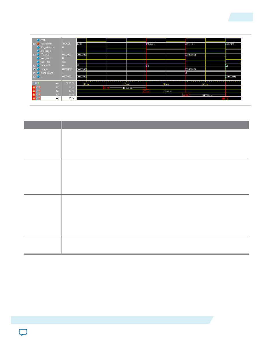
Figure 8: Initial Read Operation from the DCFIFO IP Core
Table 13: Initial Read Operation from the DCFIFO IP Core Waveform Description
State
Description
IDLE
Before reaching 35 ns, the read controller is in the
IDLE
state because the
fifo_rdempty
signal is high even when the reset signal is low (not shown in the waveform). In the IDLE
state, the
ram_addr = ff
to accommodate the increment of the RAM address in the
INCADR
state, so that the first data read is stored at
ram_addr = 00
in the
WRITE
state.
INCADR
The read controller transitions from the
IDLE
state to the
INCADR
state, if the
fifo_
rdempty
signal is low. In the
INCADR
state, the read controller drives the
fifo_rdreq
signal to high, and requests for read operation from the DCFIFO. The
ram_addr
signal is
increased by one (
ff
to
00
), so that the read data can be written into the RAM at
ram_
addr = 00
.
WRITE
From the
INCADR
state, the read controller always transition to the
WRITE
state at the next
rising clock edge. In the
WRITE
state, it drives the
ram_wren
signal to high, and enables the
data writing into the RAM at
ram_addr = 00
. At the same time, the read controller drives
the
ram_rden
signal to high so that the newly written data is output at
q
at the next rising
clock edge. Also, it increases the
word_count
signal to 1 to indicate the number of words
successfully read from the DCFIFO.
--
The same state transition continues as stated in
INCADR
and
WRITE
states, if the
fifo_
rdempty
signal is low.
UG-MFNALT_FIFO
2014.12.17
Design Example
23
SCFIFO and DCFIFO IP Cores User Guide
Altera Corporation