Altera SCFIFO User Manual
Page 15
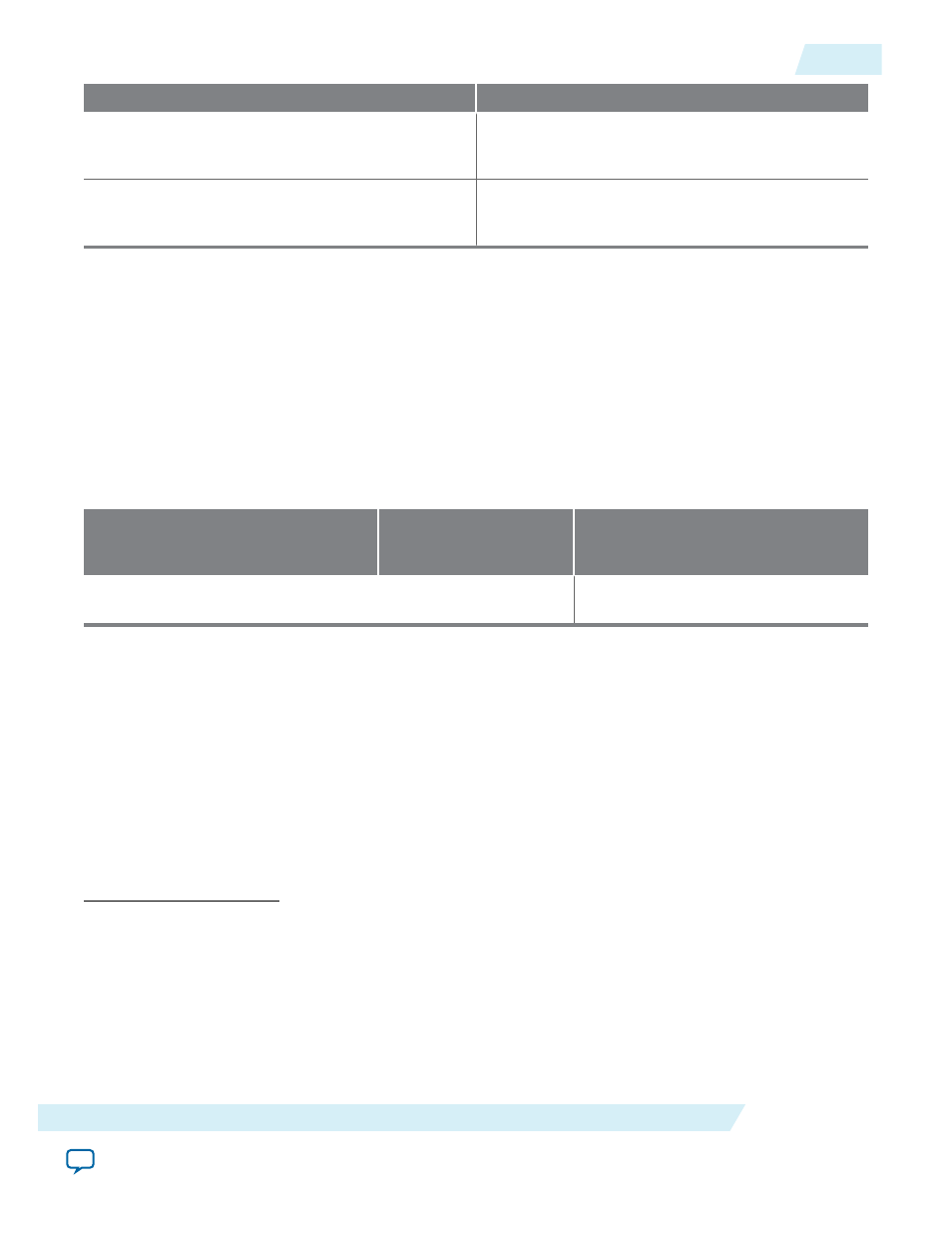
Group Setting
Comment
Minimal setting for unsynchronized clocks
This option uses two synchronization stages with
good metastability protection. It uses the medium
size and provides good f
MAX
.
Best metastability protection, best f
max
and
unsynchronized clocks
This option uses three or more synchronization
stages with the best metastability protection. It uses
the largest size but gives the best f
MAX
.
The group setting for latency and related options is available through the FIFO parameter editor. The
setting mainly determines the number of synchronization stages, depending on the group setting you
select. You can also set the number of synchronization stages you desire through the
WRSYNC_DELAYPIPE
and
RDSYNC_DELAYPIPE
parameters, but you must understand how the actual number of synchronization
stages relates to the parameter values set in different target devices.
The number of synchronization stages set is related to the value of the
WRSYNC_DELAYPIPE
and
RDSYNC_DELAYPIPE
pipeline parameters. For some cases, these pipeline parameters are internally scaled
down by two to reflect the actual synchronization stage.
Table 8: Relationship between the Actual Synchronization Stage and the Pipeline Parameters for Different
Target Devices
This table shows the relationship between the actual synchronization stage and the pipeline parameters.
Stratix II, Cyclone II, and later
Stratix and Cyclone
Devices in Low-Latency
Version
(16)
Other Devices
Actual synchronization stage = value of pipeline parameter - 2
(17)
Actual synchronization stage = value
of pipeline parameter
The TimeQuest timing analyzer includes the capability to estimate the robustness of asynchronous
transfers in your design, and to generate a report that details the mean time between failures (MTBF) for
all detected synchronization register chains. This report includes the MTBF analysis on the synchroniza‐
tion pipeline you applied between the asynchronous clock domains in your DCFIFO. You can then decide
the number of synchronization stages to use in order to meet the range of the MTBF specification you
require.
Related Information
•
Provides information about enabling metastability analysis and reporting.
•
Provides information about enabling metastability analysis and reporting.
(16)
You can obtain the low-latency of the DCFIFO (for Stratix, Stratix GX, and Cyclone devices) when the
clocks are not set to synchronized in Show-ahead mode with unregistered output in the FIFO parameter
editor. The corresponding parameter settings for the low-latency version are
ADD_RAM_OUTPUT_
REGISTER
=
OFF
,
LPM_SHOWAHEAD
=
ON
, and
CLOCKS_ARE_SYNCHRONIZED
=
FALSE
. These parameter settings are
only applicable to Stratix, Stratix GX, and Cyclone devices.
(17)
The values assigned to
WRSYNC_DELAYPIPE
and
RDSYNC_DELAYPIPE
parameters are internally reduced by 2
to represent the actual synchronization stage implemented. Thus, the default value 3 for these parameters
corresponds to a single synchronization pipe stage; a value of 4 results in 2 synchronization stages, and so
on. For these devices, choose 4 (2 synchronization stages) for metastability protection.
UG-MFNALT_FIFO
2014.12.17
SCFIFO and DCFIFO Metastability Protection and Related Options
15
SCFIFO and DCFIFO IP Cores User Guide
Altera Corporation