Altera SCFIFO User Manual
Page 22
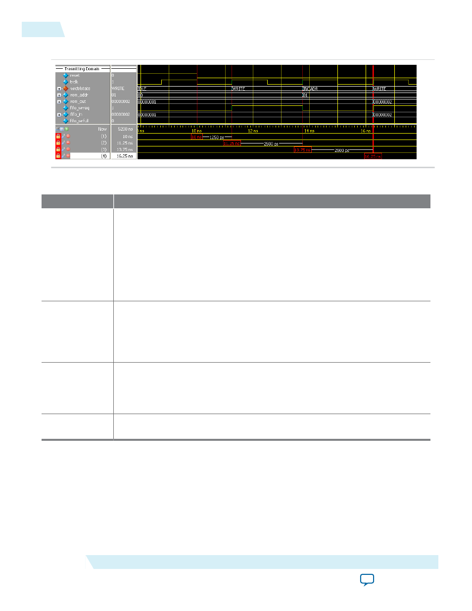
Figure 7: Initial Write Operation to the DCFIFO IP Core
Table 12: Initial Write Operation to the DCFIFO IP Core Waveform Description
State
Description
IDLE
Before reaching 10 ns, the
reset
signal is high and causes the write controller to be in
the
IDLE
state. In the
IDLE
state, the write controller drives the
fifo_wrreq
signal to
low, and requests the data to be read from
rom_addr=00
. The ROM is configured to
have an unregistered output, so that the
rom_out
signal immediately shows the data
from the
rom_addr
signal regardless of the reset. This shortens the latency because the
rom_out
signal is connected directly to the
fifo_in
signal, which is a registered input
port in the DCFIFO. In this case, the data (00000001) is always stable and pending to be
written into the DCFIFO when the
fifo_wrreq
signal is high during the
WRITE
state.
WRITE
The write controller transitions from the
IDLE
state to the
WRITE
state if the
fifo_
wrfull
signal is low after the reset signal is deasserted. In the
WRITE
state, the write
controller drives the
fifo_wrreq
signal to high, and requests for write operation to the
DCFIFO. The
rom_addr
signal is unchanged (
00
) so the data is stable for at least one
clock cycle before the DCFIFO actually writes in the data at the next rising clock edge.
INCADR
The write controller transitions from the
WRITE
state to the
INCADR
state, if the
rom_
addr
signal has not yet increased to
ff
(that is, the last data from the ROM has not been
read out). In the
INDADR
state, the write controller drives the
fifo_wrreq
signal to low,
and increases the
rom_addr
signal by 1 (00 to 01).
-
The same state transition continues as stated in IDLE and WRITE states, if the
fifo_
wrfull
signal is low and the
rom_addr
signal not yet increased to
ff
.
22
Design Example
UG-MFNALT_FIFO
2014.12.17
Altera Corporation
SCFIFO and DCFIFO IP Cores User Guide