Echelon IzoT NodeBuilder User Manual
Page 71
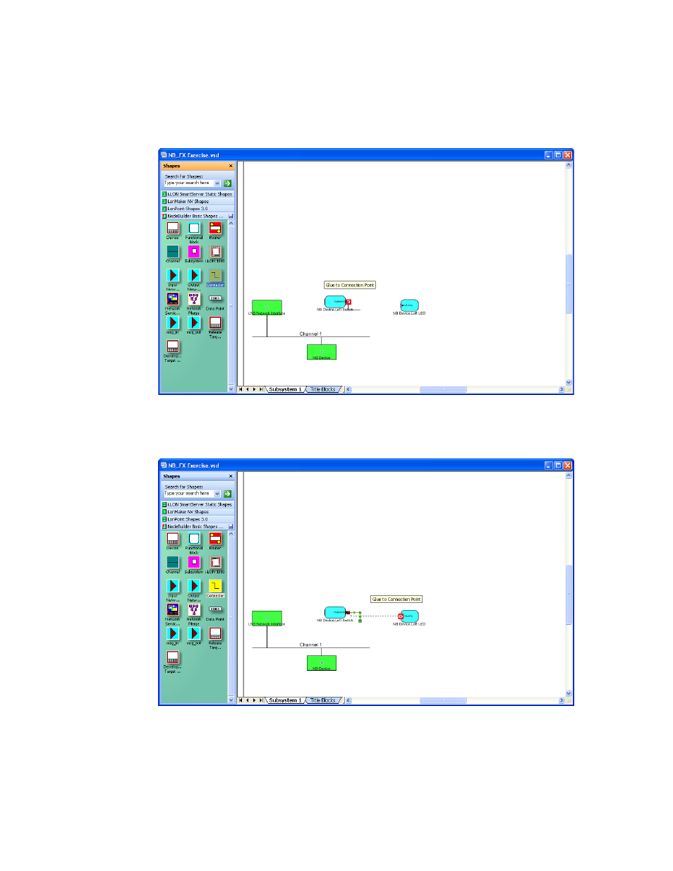
a. Drag the Connector shape from the NodeBuilder Basic Shapes 4.00 stencil to the drawing.
Position the left end of the shape over the tip of the nvoSwitch output network variable on the
Left Switch functional block before releasing the mouse button. A red box appears around
the end of the Connector shape when you have positioned it correctly over the Network
Variable shape.
b. Drag the other end of the Connector shape to the nviLamp input network variable of the
Left LED functional block until it snaps into place and a square box appears around the end
of the Connector shape. There is a brief pause as the IzoT Commissioning Tool updates the
NB Device device over the network.
9. Monitor the values of the nvoSwitch output network variable of the Left Switch functional block
and the nviLamp input network variable of the Left LED functional block. To do this, follow
these steps:
a. Right-click an empty space in the IzoT CT drawing and then select Enable Monitoring on
the shortcut menu.
IzoT NodeBuilder FX User's Guide
57