Bios chipset setup screen, Figure 4-6 – ADLINK LittleBoard 735 User Manual
Page 64
Chapter 4
BIOS Setup
58
Reference Manual
LittleBoard 735
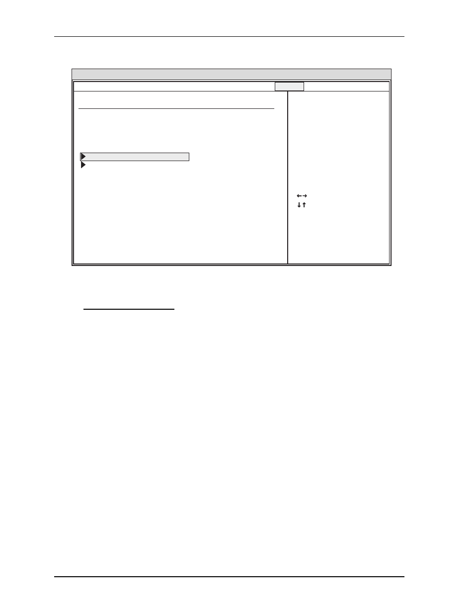
BIOS Chipset Setup Screen
Figure 4-6. BIOS Chipset Setup Screen
•
NorthBridge Configuration
♦
DRAM Frequency – [Auto; 400 MHz; 533 MHz]
♦
Configure DRAM Timing by SPD – [Disabled; Enabled]
♦
Memory Hole – [Disabled; 15MB-16MB]
♦
Boot Graphics Adapter Priority – [IGD; PCI/IGD]
♦
Internal Graphics Mode Select – [Disabled; Enabled, 1 MB; Enabled, 8 MB]
♦
Chipset Thermal Throttling – [Disabled; Enabled]
♦
DT in SPD – [Disabled; Enabled]
♦
TS on DIMM – [Disabled; Enabled]
♦
Video Function Configuration
•
DVMT Mode Select – [Fixed Mode; DVMT Mode]
- DVTM/FIXED Memory – [64MB; 128MB; Maximum DVTM]
•
Boot Display Device – [Auto; CRT; LFP; LFP+CRT]
•
Flat Panel Type – [640x480 18-bit; 800x600 18-bit; 1024x768 18-bit; 1280x1024 18-bit;
1400x1050 18-bit; 1600x1200 18-bit; 1280x768 18-bit; 1680x1050 18-bit; 1920x1200 18-bit;
1280x800 18-bit; 1280x600 18-bit; 2048x1536 18-bit]
•
Local Flat Panel Scaling [Auto; Forced Scaling; Disabled]
BIOS Setup Utility
Advanced Chipset Settings
Select Screen
Select Item
Enter Go to Sub Screen
F1 General Help
F10 Save and Exit
ESC Exit
v02.xx (C) Copyright 1985-20xx, American Megatrends, Inc.
NorthBridge Configuration
Configure North Bridge
features.
SouthBridge Configuration
WARNING: Setting wrong values in below sections
may cause system to malfunction.
Main Advanced PCIPnP Boot Security Chipset Exit
LB735_BIOS_ChipsetScreen_a