Block diagram, Figure 2-2, Functional block diagram – ADLINK LittleBoard 735 User Manual
Page 13: Littleboard 735 reference manual 7
Chapter 2
Product Overview
LittleBoard 735
Reference Manual
7
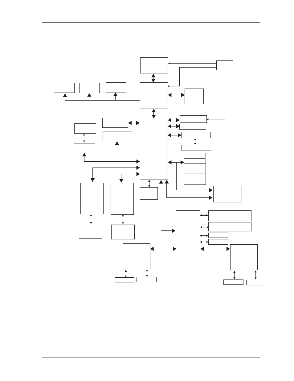
Block Diagram
shows the functional components of the LittleBoard 735.
Figure 2-2. Functional Block Diagram
LB735_BlkDiag_c
CPU
Intel Atom N270
Graphics
and
Memory Hub
(Northbridge)
82945GSE
I/O Hub
(Southbridge)
82801GBM
[ICH7-M]
DDR2
SODIMM
LVDS
Header
Super I/O
SCH3114I-NU
AC’97
CODEC
Gigabit
Ethernet
Controller
82574IT
with
Internal
Transformer
Gigabit
Ethernet
Controller
82574IT
with
Internal
Transformer
PC/104-Plus
Bus Connector
PCI - ISA
Bridge
PCI Express
Mini Card
Connector
PC/104
Connector
SATA
Connectors (2)
GLAN2
RJ45
Connector
GLAN1
RJ45
Connector
Utility 1 - PS/2 keyboard,
battery, reset, speaker
Utility 2 - PS/2 mouse,
SMBus, power button
Floppy
Parallel
COM 3
COM 4
RS232
Transceiver
RS422/485
Transceiver
and
COM 1
COM 2
RS232
Transceiver
RS422/485
Transceiver
and
VGA
Header
TV Out
Header
PCI Bus
ISA
USB Port 0
USB Port 1
USB Port 2
USB Port 3
USB Port 4
USB Port 5
USB
PCIe x1 Port1
PCIe x1 Port3
PCIe x1 Port2
LPC Bus
MDI
MDI
Clock
SMBus
IDE Header
SMBus Header
GPIO Header
IDE
Compact Flash