Memory map i/o address map, Table 3-2, Memory map – ADLINK LittleBoard 735 User Manual
Page 29: Table 3-3, I/o address map
Chapter 3
Hardware
LittleBoard 735
Reference Manual
23
Memory Map
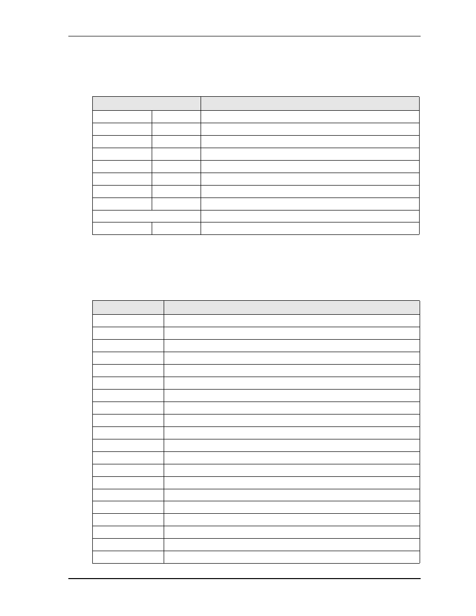
The following table provides the common PC/AT memory allocations. Memory below 000500h is used by
the BIOS.
* The BIOS contains a setting to forward memory to the ISA bus.
I/O Address Map
provides the list of I/O addresses on the LittleBoard 735.
Table 3-2. Memory Map
Base Address
Function
00000000h - 0009FFFFh
Conventional Memory
000A0000h - 000AFFFFh
Graphics Memory
000B0000h -
000B7FFFh
Mono Text Memory
000B8000h -
000BFFFFh
Color Text Memory
000C0000h -
000CFFFFh
Standard Video BIOS
000D0000h - 000DFFFFh
Reserved for Extended BIOS*
000E0000h -
000EFFFFh
Extended System BIOS Area
000F0000h -
000FFFFFh
System BIOS Area (Storage and RAM Shadowing)
Top 0, 1, or 8MB of DRAM
Integrated Graphics Memory
FFE00000h -
FFFFFFFFh
System Flash
Table 3-3. I/O Address Map
Address (hex)
Subsystem
0000-000F
Primary DMA Controller
0020-0021
Master Interrupt Controller
0040-0043
Programmable Interrupt Timer (Clock/Timer)
0060
Keyboard Controller
0061
NMI, Speaker control
0063
NMI Controller
0064
Keyboard Controller
0065
NMI Controller
0067
NMI Controller
0070-007F
CMOS RAM, NMI Mask Reg, RT Clock
0080
System reserved
0081-0083
DMA Page Registers
0084-0086
System reserved
0087
DMA Page Register
0088
System reserved
0089-008B
DMA Page Registers
008C-008E
System reserved
008F
DMA Page Register
0090-0091
System reserved
0092
Fast A20 gate and CPU reset