Interrupt channel assignments, Table 3-1 – ADLINK LittleBoard 735 User Manual
Page 28
Chapter 3
Hardware
22
Reference Manual
LittleBoard 735
♦
External Battery Input
♦
Dual LED interfaces for Gigabit Ethernet
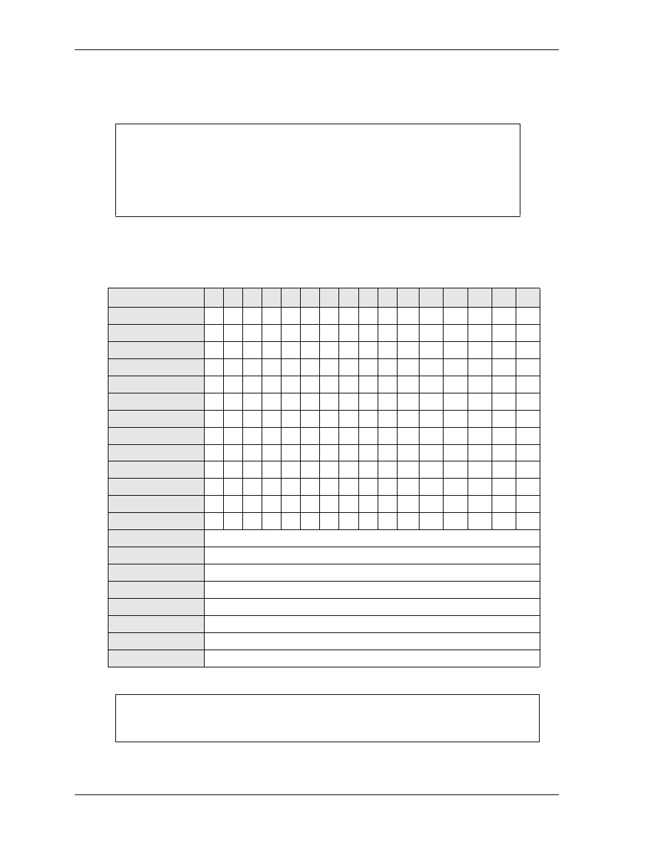
Interrupt Channel Assignments
The interrupt channel assignments are shown in
Legend: D = Default, O = Optional, X = Fixed
NOTE
ADLINK Technology, Inc. only supports the features and options described in
this manual. The main integrated circuits (ICs) on the LittleBoard 735 may
provide more features or options than are listed in this manual, and those
features and options may not function as specified in the IC documentation.
This chapter does not include pinout tables for standard headers and connectors
such as PC/104, Ethernet RJ45, 40-pin IDE, Floppy, and Compact Flash.
Table 3-1. Interrupt Channel Assignments
Device vs IRQ No.
0
1
2
3
4
5
6
7
8
9
10
11
12
13
14
15
Timer X
Keyboard
X
Secondary Cascade
X
COM1
O D
O
O
COM2
D O
O
O
COM3
O O
O
D
COM4
O O
D
O
Floppy
X
Parallel
O
D
O
O
RTC
X
IDE
D
Math Coprocessor
X
PS/2 Mouse
X
PCI INTA
Automatically Assigned
PCI INTB
Automatically Assigned
PCI INTC
Automatically Assigned
PCI INTD
Automatically Assigned
PCI INTE
Automatically Assigned
PCI INTF
Automatically Assigned
PCI INTG
Automatically Assigned
PCI INTH
Automatically Assigned
NOTE
The PCI IRQs for the Ethernet, Video, and Internal Local Bus are automatically
assigned by the BIOS Plug and Play logic. Local ISA IRQs assigned during
initialization can not be used by external devices.