Tv-out interface, Table 3-16, Tv-out pin signals (j36) – ADLINK LittleBoard 735 User Manual
Page 43
Chapter 3
Hardware
LittleBoard 735
Reference Manual
37
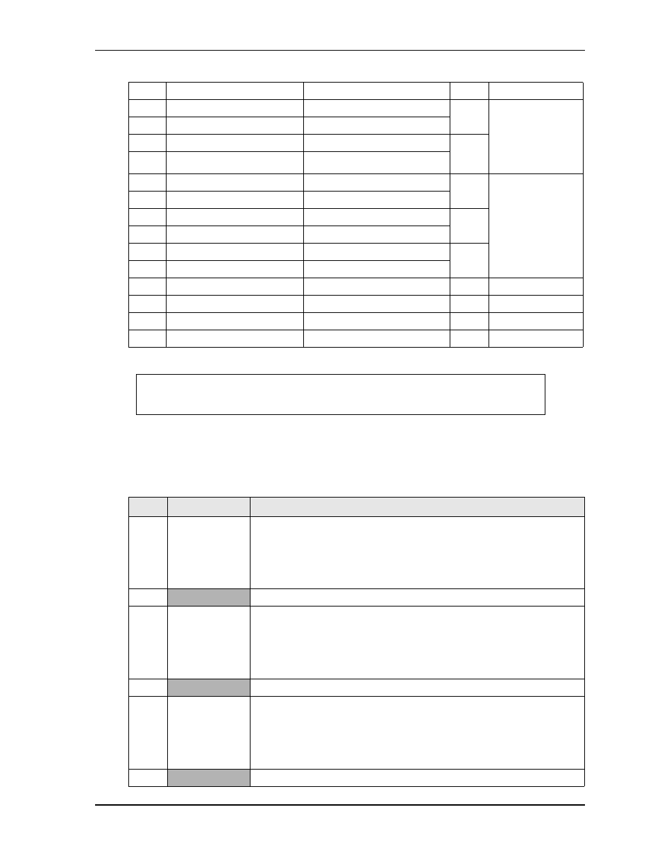
Note: The shaded table cells denote power or ground.
TV-Out Interface
describes the pin signals of the TV-Out interface, which provides a 6-pin header with 2 rows,
odd/even sequence (1, 2), and 0.100" (2.54mm) pitch.
Note: The shaded table cells denote ground.
16
LVDD_EN
Enable Panel Power
NA
NA
17
LACLK_P
Clock Positive Output
Clock
Channel 1
18
LACLK_N
Clock Negative Output
19
Not Supported
N/A
N/S
20
Not Supported
N/A
21
LADATA2_P
Data Positive Output
2
22
LADATA2_N
Data Negative Output
23
LADATA1_P
Data Positive Output
1
24
LADATA1_N
Data Negative Output
25
LADATA0_P
Data Positive Output
0
26
LADATA0_N
Data Negative Output
27
L_DDC_CLK
Display Data Channel Clock
NA
NA
28
L_DDC_DAT
Display Data Channel Data
NA
NA
29
LVDS_BKLT_EN
Enable Backlight Inverter
NA
NA
30
NC
Not Connected
NA
NA
NOTE
Pins 5-14 constitute 2
nd
channel interface of two channels. Pins 15-26 constitute
1
st
channel interface of two channels, or a single channel interface.
Table 3-16. TV-Out Pin Signals (J36)
Pin #
Signal
Description
1
TVDAC A
TVDAC Channel A Output:
TVDAC_A supports the following:
Composite: CVBS signal
Component: Chrominance (Pb) analog signal
2
TV_GND
Ground
3
TVDAC B
TVDAC Channel B Output:
TVDAC_B supports the following:
S-Video: Luminance analog signal
Component: Luminance (Y) analog signal
4
TV_GND
Ground
5
TVDAC C
TVDAC Channel C Output:
TVDAC_C supports the following:
S-Video: Chrominance analog signal
Component: Chrominance (Pr) analog signal
6
TV_GND
Ground
Table 3-15. LVDS Interface Pin Signals (J26) (Continued)