Serial interfaces, Figure 3-1, Rs485 serial port implementation – ADLINK LittleBoard 735 User Manual
Page 32
Chapter 3
Hardware
26
Reference Manual
LittleBoard 735
Serial Interfaces
Two MAX213ECAI+ chips and two LTC1334CG#PBF chips provide the circuitry for the four serial ports.
The two MAX213ECAI+ chips provide the RS232 mode, and the two LTC1334CG#PBF chips provide the
RS485/RS422 modes. The four serial ports support the following features:
•
Four individual 16550-compatible UARTs
•
Programmable word length, stop bits and parity
•
16-bit programmable baud rate generator
•
Interrupt generator
•
Loop-back mode
•
Four individual 16-bit FIFOs
•
Serial A Interface (J11)
♦
Serial Port 1 (COM1) supports RS232/RS485/RS422 and full modem support
♦
Serial Port 2 (COM2) supports RS232/RS485/RS422 and full modem support
•
Serial B Interface (J12)
♦
Serial Port 3 (COM3) supports RS232/RS485/RS422 and full modem support
♦
Serial Port 4 (COM4) supports RS232/RS485/RS422
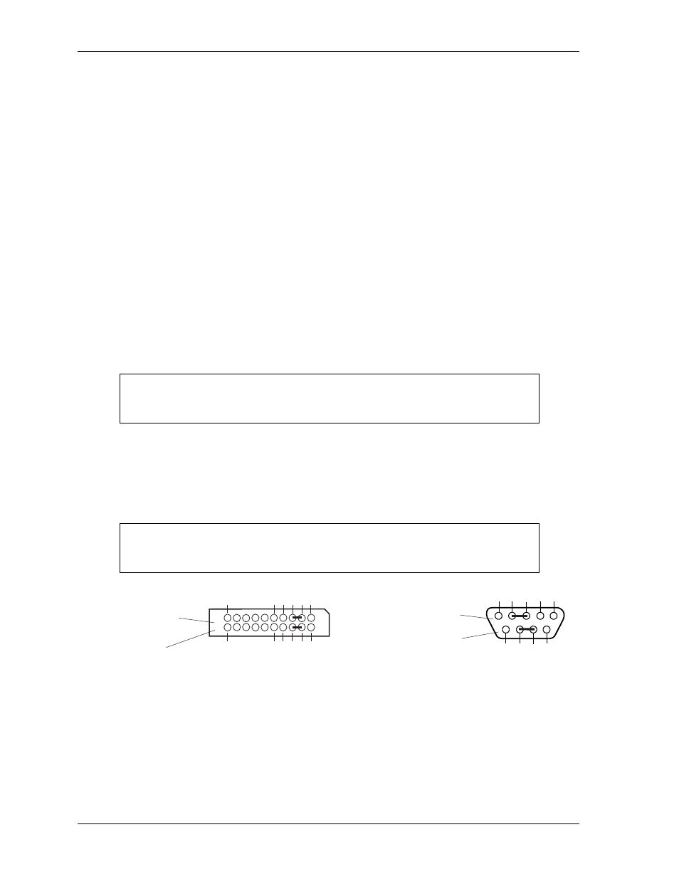
To implement the two-wire RS485 mode on any serial port, you must tie the equivalent pins together for
each port.
For example, on Serial Port 1, tie pin 3 to pin 5 and pin 4 to pin 6 at the Serial A interface header (J11) as
shown in
. As an alternate, tie pin 2 to pin 3 and pin 7 to pin 8 at the DB9 serial connector for
Serial Port 1 as shown in
. Refer also to the following tables for the specific pin signals on each
connector.
Figure 3-1. RS485 Serial Port Implementation
defines the pins and corresponding signals for the Serial A interface header (Serial Ports 1 and 2)
defines the pins and corresponding signals for the Serial B interface header (Serial Ports 3 and
4).
Both Serial A and B headers use 20 pins, 2 rows, odd/even sequence (1, 2) with 0.100" (2.54mm) pitch.
NOTE
The RS232 and RS485/RS422 modes can be selected for any serial port in BIOS
Setup under the Advanced menu. However, the RS232 mode is the default
selection (Standard) for any serial port.
NOTE
The RS422 mode uses a four-wire interface and does not require any pins tied
together, but you must select RS485 in BIOS Setup and make sure the
termination jumper is removed.
Serial A Interface (J11)
for Serial Port 1
(or COM1 Port)
1
2
3
4
5
6
7
8
9
10
20
19
Top View
Standard DB9 Serial
Port Connector (Male)
Front View
Or
LB735RS485conn_b
5
4
3
2
1
9
8
7
6