Figure 3-2, Oops! jumper connection, Table 3-21 – ADLINK LittleBoard 735 User Manual
Page 46: Smbus pin signals (j45), Smbus interface, Oops! jumper (bios recovery), Remote access
Chapter 3
Hardware
40
Reference Manual
LittleBoard 735
Note: The shaded table cells denote power or ground.
SMBus Interface
Compatible with most I2C devices, this interface allows the processor to communicate with SMBus slave
peripherals through the Host SMBus controller on the ICH7-M.
lists the pin signals for the SMBus interface (J45), which provides a 5-pin, single-row header
with 0.49" pitch.
Note: The shaded table cells denote power or ground.
Oops! Jumper (BIOS Recovery)
The Oops! jumper is provided in the event the BIOS settings you have selected prevent you from booting the
system. By using the Oops! jumper you can prevent the current BIOS settings in the EEPROM from being
loaded, forcing the use of the default settings. Connect the DTR pin to the RI pin on serial port 1 (COM 1)
prior to boot up to prevent the present BIOS settings from loading. After booting with the Oops! jumper in
place, remove the Oops! jumper and go into BIOS Setup. Change the desired BIOS settings, or select the
default settings, and save changes before rebooting the system.
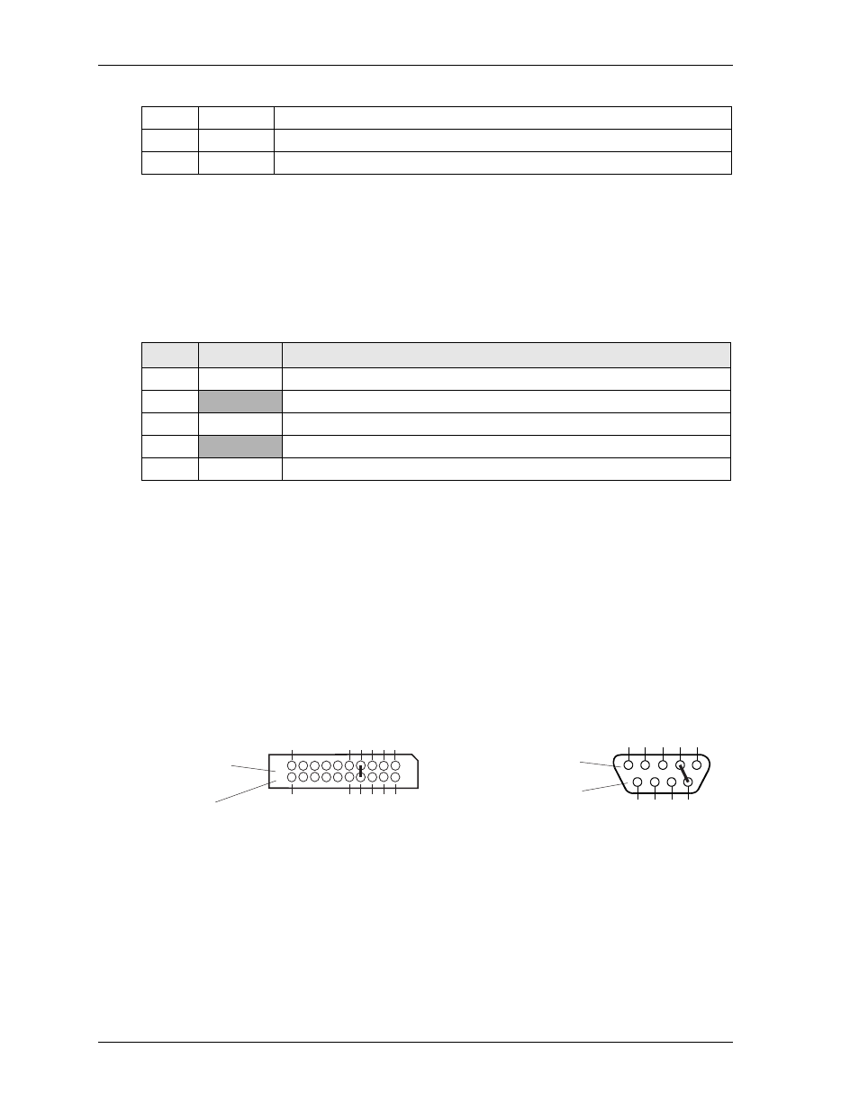
To convert the Serial A interface to an Oops! jumper, short together the DTR (7) and RI (8) pins on the
Serial A (J11) header for Serial Port 1. As an alternate, short the equivalent pins, 4 and 9, on the Serial Port
1 DB9 connector as shown in
.
Figure 3-2. Oops! Jumper Connection
Remote Access
The LittleBoard 735 supports the remote access (or console redirection) feature. This I/O function is
provided by an ANSI-compatible serial terminal, or the equivalent terminal emulation software running on
another system. This can be very useful when setting up the BIOS on a production line for systems that are
not connected to a keyboard and display.
8
GPO2
User defined
9
GPI3
User defined
10
GPO3
User defined
Table 3-21. SMBus Pin Signals (J45)
Pin #
Signal
Description
1
SCL
SMBus Clock Reset
2
GND
Ground
3
SDA
SMBus Data Reset
4
VCC
+3.3 Volts DC +/ 5%
5
ALERT
SMBus Alert
Table 3-20. User GPIO Pin Signals (J40) (Continued)
Serial A Interface (J11)
for Serial Port 1
(or COM1 Port)
1
2
3
4
5
6
7
8
9
10
20
19
Top View
Standard DB9 Serial
Port Connector (Male)
Front View
Or
LB735Oopsjumper_b
5
4
3
2
1
9
8
7
6