Optional cpu fan glan1 led glan2 led, Table 3-22, Optional cpu fan (j34) – ADLINK LittleBoard 735 User Manual
Page 48: Table 3-23, Table 3-24
Chapter 3
Hardware
42
Reference Manual
LittleBoard 735
Optional CPU Fan
lists the pin signals of the optional CPU Fan interface, which provides a 3-pin, single-row header
with 0.100" (2.54mm) pitch.
Note: The shaded table cells denote power or ground.
GLAN1 LED
lists the pin signals of the J47, external GLAN1 LED interface, which provides a
5-pin, single-row header with 0.049" (1.24mm) pitch.
Note: The shaded table cells denote power or ground. The * symbol indicates the signal is Active Low.
GLAN2 LED
lists the pin signals of the J48, external GLAN2 LED interface, which provides a
5-pin, single-row header with 0.049" (1.24mm) pitch. .
Note: The shaded table cells denote power or ground. The * symbol indicates the signal is Active Low.
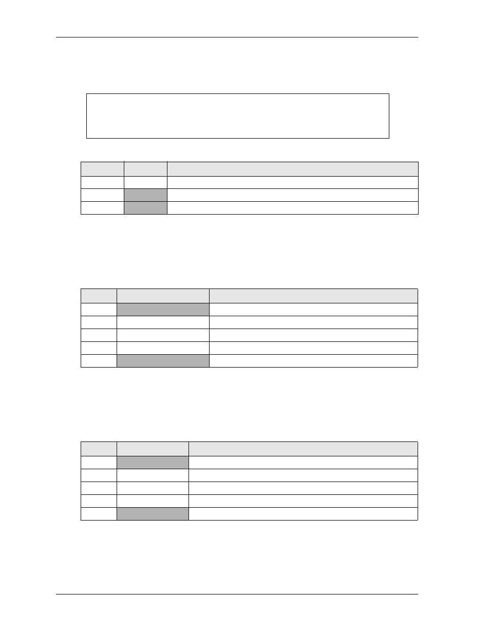
CAUTION
The voltage to the fan should not exceed 130mA on the LB-735-R-18
model and 250mA on the LB-735-P-18 and LB-735-F-18 models or
significant damage to the board may occur. See the LittleBoard 735
Hardware Release Notes for more details.
Table 3-22. Optional CPU Fan (J34)
Pin #
Signal
Description
1
Fan_Tach
Fan Tachometer – This signal monitors the fan speed
2
VCC
+5.0 volts DC +/- 5%
3
GND
Ground and Modulation – This signal controls the fan speed
Table 3-23. Ethernet External LED Pin Signal Descriptions (J47)
Pin #
Signal
Description
1
+V3.3_S5
+3.3 Volts Ethernet Power
2
ACT_LED1*
Ethernet Activity
3
SPEED_LED1*
Ethernet Speed
4
LINK1000_LED1*
Ethernet Connection
5
GND
Ethernet Ground
Table 3-24. Ethernet External LED Pin Signal Descriptions (J48)
Pin #
Signal
Description
1
+V3.3_S5
+3.3 Volts Ethernet Power
2
ACT_LED2*
Ethernet Activity
3
SPEED_LED2*
Ethernet Speed
4
LINK1000_LED2*
Ethernet Connection
5
GND
Ethernet Ground