Power interfaces, Table 3-17, Power-in interface pin signals (j19) – ADLINK LittleBoard 735 User Manual
Page 44: Table 3-18, Atx power-on interface pin signals (j30), Table 3-19, Power button interface pin signals (j46)
Chapter 3
Hardware
38
Reference Manual
LittleBoard 735
Power Interfaces
Power-In Interface
The LittleBoard 735 derives all of its onboard voltages from an external DC power supply through the J10
Power-In header and requires only +5 volts for operation.
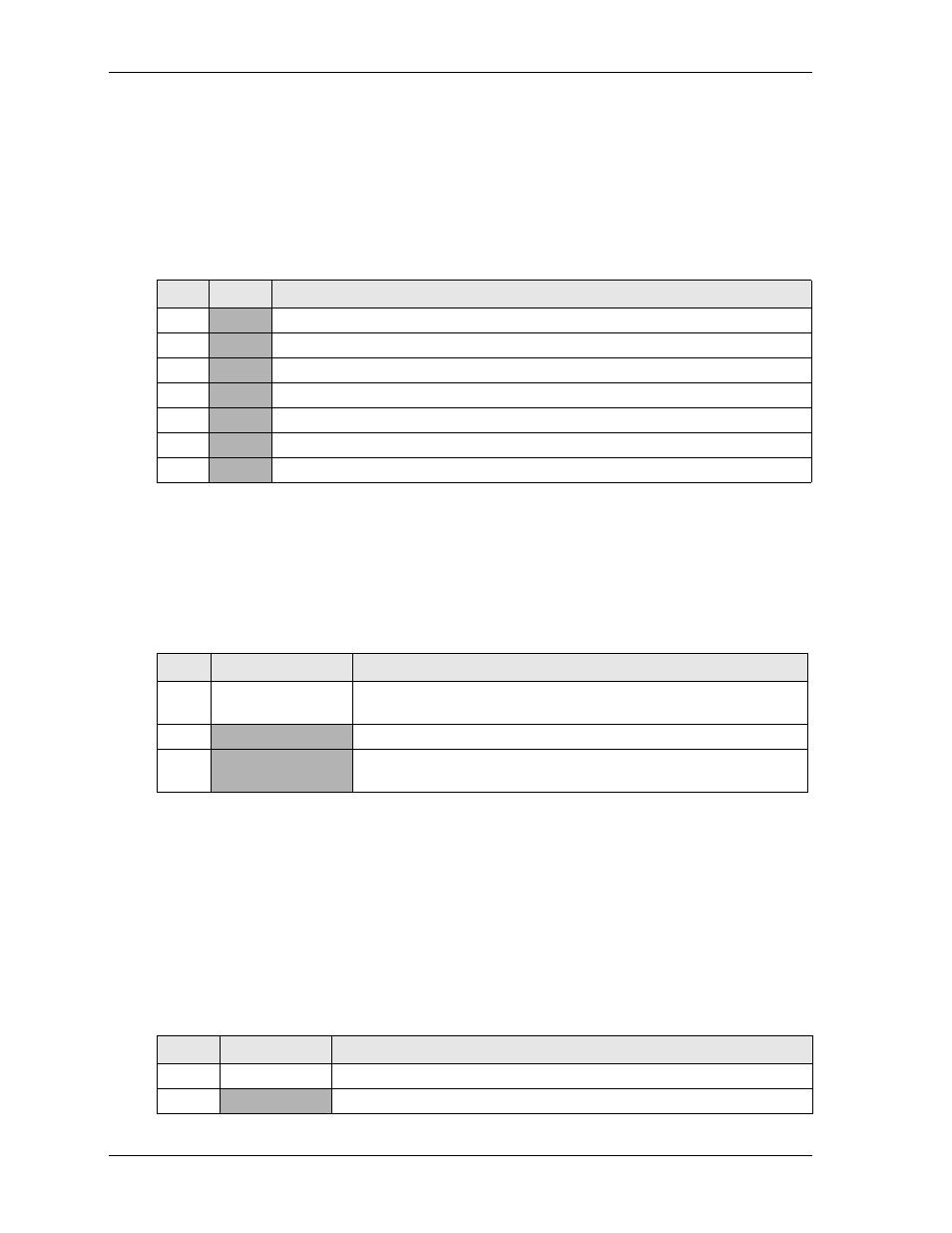
lists the pin signals for the J19 power-in interface, which provides a 7-pin, single-row header
with 0.156" (3.96mm) pitch.
Note: The shaded table cells denote power or ground.
ATX Power-On Interface
This 3-pin header (J30) provides ATX control of the power supply.
lists the pin signals for the ATX Power-On interface, which provides a 3-pin, single-row header
with 0.100" (2.54mm) pitch.
Note: The shaded table cells denote power or ground. The * symbol indicates the signal is Active Low.
Power Button and Reset Switch Interface
A power button signal is provided by connecting ground to pin-1 on this header (J46). A hardware reset
switch signal is provided by connecting ground to pin 3 on this header. Press and hold the green button on
the power button cable for at least four seconds to power off the system. To power on the system, press and
release the green button and wait for the system to boot. To perform a hardware reset, press and release the
red button on the power button cable.
lists the pin signals for the J46 Power Button and Reset Switch interface, which provides a 5-pin,
single-row header with 0.100" (2.54mm) pitch.
Table 3-17. Power-In Interface Pin Signals (J19)
Pin #
Signal
Description
1
+5V
+5.0 Volts – This +5.0 volts DC +/- 5% is the only voltage required for operation.
2
GND
Ground
3
GND
Ground
4
+12V
+12 Volts – This +12 volts is for the PC/104, PC/104-Plus, and LVDS power only.
5
+3.3V
+3.3 Volts – This +3.3 volts is for PC/104-Plus Bus power only (optional).
6
GND
Ground
7
+5V
+5.0 Volts – This +5.0 volts DC +/- 5% is the only voltage required for operation.
Table 3-18. ATX Power-On Interface Pin Signals (J30)
Pin #
Signal
Description
1
PS_ON*
Power Supply On – This signal provides the LittleBoard 735 ATX
control of the power supply.
2
GND
Ground
3
VCC5_ATX_STBY +5V Standby (+5V, 500mA) – This voltage is supplied from the ATX
power supply and is required for ATX operation.
Table 3-19. Power Button Interface Pin Signals (J46)
Pin #
Signal
Description
1
PWRBTN*
Power Button input (connect between pins 1 & 2)
2
GND
Ground