Utility interfaces – ADLINK LittleBoard 735 User Manual
Page 35
Chapter 3
Hardware
LittleBoard 735
Reference Manual
29
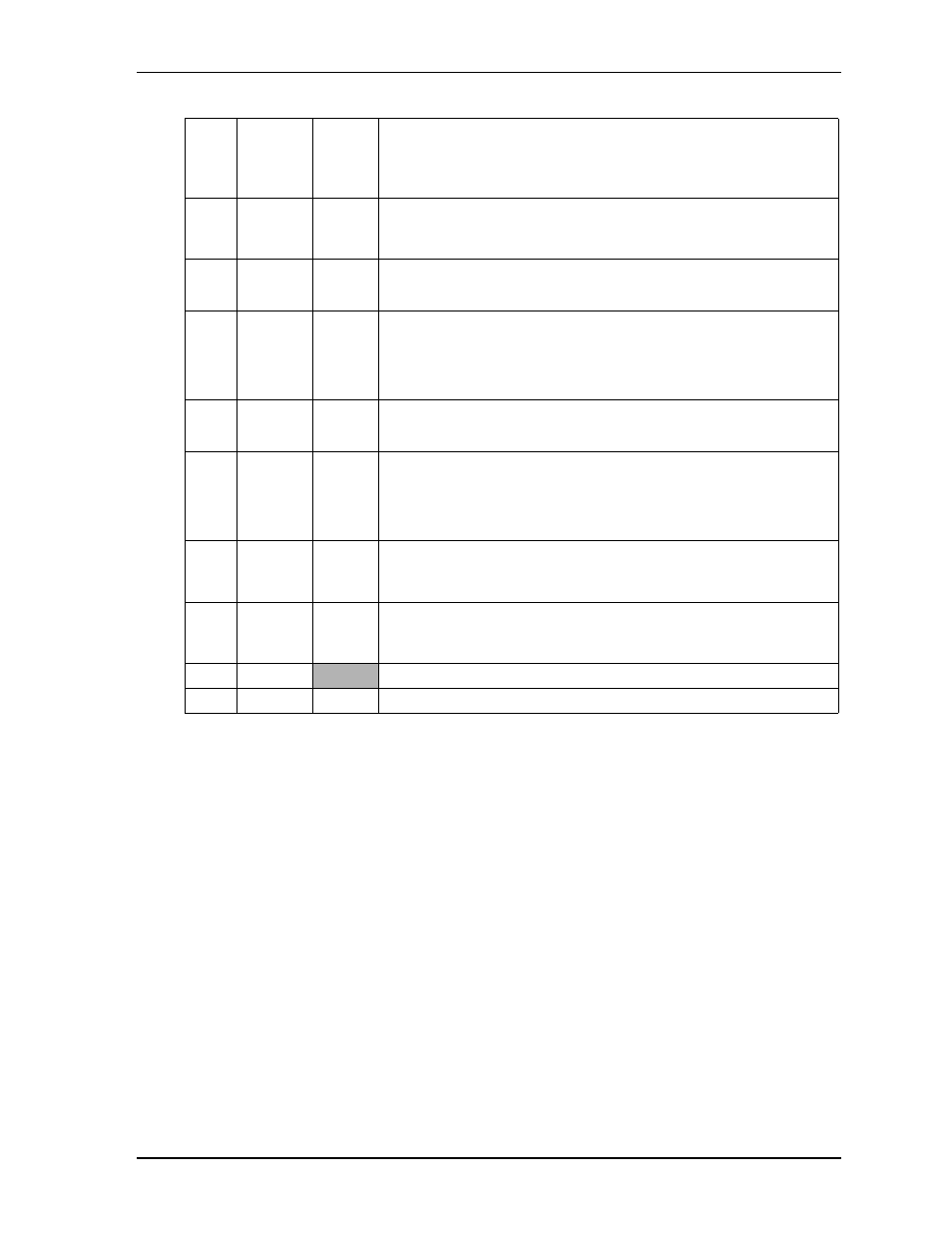
Note: The shaded table cells denote ground. Signals are listed in the table with RS232 first, followed by
RS485/RS422. The * symbol indicates the signal is Active Low.
Utility Interfaces
The Utility interfaces consist of two headers that provide the standard interface signals for the following
devices:
•
Utility 1 (J15)
♦
PS/2 Keyboard
♦
External battery
♦
Reset Switch
♦
Power-On LED
♦
Speaker
•
Utility 2 (J13)
♦
PS/2 Mouse
♦
SMBus
♦
Power button
11
1
(COM4)
DCD4* Data Carrier Detect 4 – Indicates external serial communications
device is detecting a carrier signal (i.e., a communication channel is
currently open). In direct connect environments, this input will be
driven by DTR4 as part of the DTR/DSR handshake.
12
6
DSR4* Data Set Ready 4 – Indicates external serial communications device is
powered, initialized, and ready. Used as hardware handshake with
DTR4 for overall readiness to communicate.
13
2
RXD4
RX4-
Receive Data 4 – Serial port 4 receive data in
RX4- – If in RS485 or RS422 mode, this pin is Receive Data 4 -.
14
7
RTS4*
TX4+
Request To Send 4 – Indicator to serial output port 4 is ready to
transmit data. Used as hardware handshake with CTS4 for low level
flow control.
TX4+ – If in RS485 or RS422 mode, this pin is Transmit Data 4 +.
15
3
TXD4
TX4-
Transmit Data 4 – Serial port 4 transmit data out
TX4- – If in RS485 or RS422 mode, this pin is Transmit Data 4 -.
16
8
CTS4*
RX4+
Clear To Send 4 – Indicator to serial port 4 that external serial
communications device is ready to receive data. Used as hardware
handshake with RTS4 for low level flow control.
RX4+ – If in RS485 or RS422 mode, this pin is Receive Data 4 +.
17
4
DTR4*
Data Terminal Ready 4 – Indicates this Serial port is powered,
initialized, and ready. Used as hardware handshake with DSR4 for
overall readiness to communicate.
18
9
RI4*
Ring Indicator 4 – Indicates external serial communications device is
detecting a ring condition. Used by software to initiate operations to
answer and open the communications channel.
19
5
GND
Ground
20
NC
NC
Not connected
Table 3-6. Serial B Interface Pin Signals (J12) (Continued)