Carrier 07D User Manual
Carrier 06d,07d, And o, Installation instructions
Attention! The text in this document has been recognized automatically. To view the original document, you can use the "Original mode".
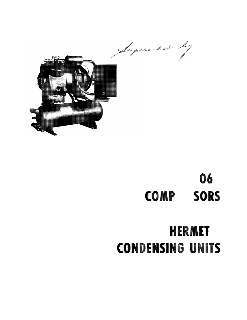
Table of contents
Document Outline
- 06D,07D
- CONTENTS
- z
- 5
- 5
- 5
- o
- 5
- 5
- 5
- 5
- m
- INSPECT THE SITE Preliminary Survey
- INSPECT SHIPMENT FOR LOSS AND DAMAGE
- SET THE UNIT IN PLACE
- CODE COMPLIANCE
- ELECTRICAL REQUIREMENTS
- Water-Cooled Condensing Unit Control T ransformers
- POWER AND CONTROL CIRCUIT SCHEMATIC
- Fig, 14 - Wiring Label 07D Condensing Units, 06D Compressor Units (3-Phase)
- Fig. 16 - Field Wiring for 06D, 07D Units
- Fig. 16 - Field Wiring for 06D, 07D Units (Confd)
- PIPING AND ACCESSORIES
- Elimination of Pipe Vibration
- Time Guard Control Operation
- Starting Sequence of Time Guard Control (Single Pump-Out Arrangement Shown)
- Operating Condition of Time Guard Control (Single Pump-Out Arrangement Shown)
- Stopping Sequence of Time Guard Control (Single Pump-Out Arrangement Shown)
- Shut-Off Valves
- Crankcase Heater
- Liquid Line Strainer-Drier
- Flare Connections
- Soldering and Brazing Piping to Valves
- Water Regulating Valves (Water-Cooled Units Only)
- Liquid Line Solenoid Valve (Field Supplied)
- Liquid Line Sight Glass
- Condenser Water Connections
- The Halide Leak Detector
- LEAK TEST THE SYSTEM
- DEHYDRATE THE SYSTEM Preparation
- #
- Description and Use of the Vacuum Indicator
- Procedure for Dehydrating the System
- CHECK REFRIGERANT CHARGE
- CHECKING OPERATIONS
- Dual Pressurestat
- INITIAL START-UP INSTRUCTIONS
- Water-Cooled Units
- Lubrication
- Water Valve Adjustment (Water-Cooled Units Only)
- Factory Oil Charge
- Fig. 22 - Oil Level Measurement 2 Cylinder Compressors
- 07DA210,112,215 ELECTRICALLY OPERATED CAPACITY CONTROL DEVICE
- Solenoid Valve Electrical Characteristics
- Fig. 24 - 07DA210,! 12,215 Compressor with Cylinder Head Unloading - Cylinder Bank Loaded
- m