Pressure operated capacity control valve operation, 06d,07d, Carrier – Carrier 07D User Manual
Page 31: Installation
Attention! The text in this document has been recognized automatically. To view the original document, you can use the "Original mode".
Carrier
INSTALLATION
06D,07D
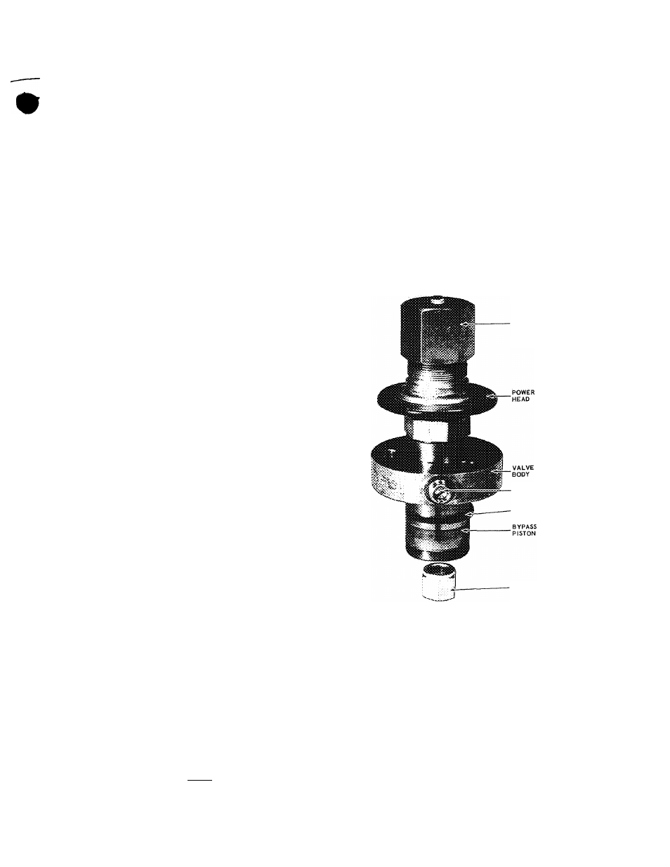
Pressure Operated Capacity Control Valve
Operation
This valve is self-contained in that no wiring
or external controls such as pressurestats or
thermostats are needed as on the solenoid ca
pacity control valve.
This valve is interchangeable with the sole
noid capacity control valve now used on the
6D compressors.
It is also interchangeable between the 06D and
06E compressors.
This valve is a self-actuated cylinder head by
pass type which is suction pressure operated.
The valve operation is such that the controlled
cylinders will not load up until a differential
of 25 psi between suction and discharge pres
sure is established.
There can be a control valve in each side bank
of the six cylinder compressors. Each of the
control valves will load or unload two cylinders
in a single bank of the compressor by allowing
the discharge gas to bypass to the suction side
thru the bypass port. The unloaded cylinders
then operate thru no pressure differential, thus
consuming very little power.
When the suction pressure drops due to decrease
in load, the poppet valve will snap open, as shown
in Fig. 25A. The discharge gas behind the piston
will now bleed out to the suction manifold, re
ducing the pressure behind the bypass piston and
allowing the bypass piston spring to pull the pis
ton back against the valve body. The bypass pis
ton port will then open allowing discharge gas
to recirculate back to the suction manifold.
When the suction pressure is above the valve
set point, the poppet valve will be closed, as
shown in Fig. 25B. Discharge gas will now bleed
into the valve chamber. The pressure will then
overcome the bypass valve spring tension and
force the piston forward, sealing the bypass
port. The two cylinders controlled by this valve
will now run fully loaded.
The check valve in the valve plate will close
when the cylinder bank is unloaded, isolating the
individual cylinder bank from the discharge man
ifold. When the bank loads up, the discharge gas
pressure will force open the check valve, allow
ing the gas to pass into the discharge manifold.
Pumpdown control is NOT recommended when
using these valves because of a bleed in the
differential chamber. This device will equalize
the compressor upon shutdown within 50 psi dif
ferential very quickly so that on start-up the
compressor will have very little head pressure
to start against. There is a possibility of short
cycling on pumpdown because of a short equal
ization time. Therefore, we recommend single
pumpout or liquid line solenoid drop with crank
case heaters.
The control load up or set point (Fig. 26) is ad
justable from -40 F (0-psig) to +50 F (85-psig)
and is set in the field for individual job require
ments. The set point adjustment is made by
turning clockwise to increase the control pres
sure (load up) and counterclockwise to decrease
the control pressure point.
SET POINT
ADJUSTMENT
DIFFERENTIAL
ADJUSTMENT
BYPASS
PISTON RING
DIFFERENTIAL
SCREW
SEALING CAP
Fig. 26 - Capacity Control Valve
To Adjust - The set point head should be turned
clockwise down to the bottom stop. The coun
terclockwise turns can be determined by using
the curve in Fig. 27. If the desired load up point
is known, the number of turns can be picked
off the curve.
The differential adjustment (Fig. 26) will vary
the pressure difference between the cut-in and
cutout point from 6- to 22-psi. This differential
adjustment is made by removing the sealing
cap and turning the inside screw clockwise to
increase the differential and counterclockwise
to decrease the differential.
31