06d,07d, Carrier, Installation – Carrier 07D User Manual
Page 22
Attention! The text in this document has been recognized automatically. To view the original document, you can use the "Original mode".
06D,07D
INSTALLATION
Carrier
■ L|
EVAPORATOR
INTERLOCK
CONTACTS,N.O.
----
OFF
CONO AUX
---
LOW
PRESS.
SWITCH
CONTROL
THERMOSTAT
---------
*^^-0------
SAFETY
DEVICE
CONTACTS,N.C.
PUMPOUT RELAY
M" AUX
J/_
CONTACTS,N.OT
POR
CONTACTS,N.O.
TR
TR
CONTACTS, N.O.
4^—---------
LIQ SOL VALVE
CONTACTS,N.C.
2. Operating Condition
Time: 0 Min 15 Sec
Timer switch plunger has dropped off the
cam node and the contacts have switched to
positions A-Ai and B-Bi. Timer motor stops
running since TR N.C. contacts are open.
O
O-
a
■ Ö
—Cj-O—<•
HIGH
PRESS..
SWITCH
TIMER RELAY
COND AUX
AUX CONTACTS,NO.
—
#—
COMPRESSOR
TIMER MOTOR CAM
1/5 RPM, 15 SEC CAM NODE
O
TIMER MOTOR
Timer relay (TR) remains energized thru
TR N.O. contacts, which are now closed.
Compressor motor starter is energized thru
timer switch contacts A-Ai and compressor
starts. Compressor continues to run unless
circuit is broken by action of control ther
mostat or safety devices.
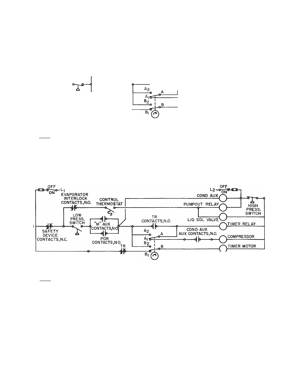
Operating Condition of Time Guard Control (Single Pump-Out Arrangement Shown)
CONTACTS, N.C.
3. Stopping Sequence
Time: Any time after 15 seconds
Timer switch plunger is still in position of
having just dropped off the cam node, since
timer motor has not been running, and switch
contacts are in position A-Ai and B-Bi.
Thermostat opens when cooling load is sat
isfied. Liquid solenoid valve (SV) is de
energized and closes. Pumpout relay (POR)
is de-energized, and its contacts open. The
timer relay (TR) and compressor continue
to operate thru compressor starter auxiliary
contacts ”M" until system pumps down and
low-pressure switch opens. Then compres-
TIMER MOTOR CAM
1/5 RPM, 15 SEC CAM NODE
sor and condenser auxiliaries stop and relay
TR is de-energized. TR N.C. contacts close
and timer motor (TM) is energized thru
switch contacts B-Bi and starts to run.
The TM timer will switch again to position
A-A2 and B-B
2
after 4 min 45 sec elapse.
Thus, at least 4 min 45 sec must elapse after
a shutdown before the compressor can begin
its restart sequence, if the cooling thermo
stat is closed. A total of 5 min will elapse
before the compressor can restart. Each
compressor restart is preceded by 15 sec
operation of the condensing equipment.
This reverts to conditions at time 0 min 0 sec.
Stopping Sequence of Time Guard Control (Single Pump-Out Arrangement Shown)
22