The halide leak detector, Leak test the system, Dehydrate the system preparation – Carrier 07D User Manual
Page 24: 06d,07d, Carrier, Installation
Attention! The text in this document has been recognized automatically. To view the original document, you can use the "Original mode".
06D,07D
INSTALLATION
Carrier
COOLING TOWER OR
CITY WATER
COOLING TOWER
CITY WATER
COOLING TOWER
CITY WATER
PRECAUTIONS: Do not use the compres
sor to build up pressure. If used to com
press air, overheating and damage may
result.
DO NOT USE OXYGEN TO BUILD UP PRES
SURE. Use a refrigerant or a dry stable gas
such as nitrogen or carbon dioxide instead.
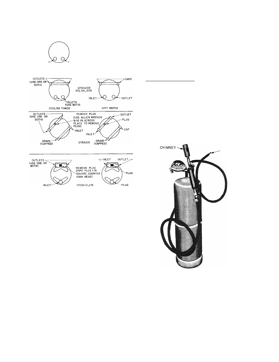
The Halide Leak Detector
The halide leak detector in Fig. 19 consists of a
burner, needle valve, suction tube, and a chim
ney with a copper reaction plate. Some torches
use alcohol and others propane as fuel.
To use the leak detector:
1. Adjust the flame so the top of the flame cone
is level with or slightly above the chimney.
2.
Place the end of the suction tube at the point
to be tested. The tube pulls in a sample of
air to the burner where the refrigerant is
decomposed by reaction with the copper plate.
3. Observe color of the flame. Small leaks give
a greenish tint and large ones a vivid blue.
Fig. 18 - Water-Cooled Condensing Units
Condenser Water Connections
LEAK TEST THE SYSTEM
1. Charge the system to 40 psi with dry nitrogen
or carbon dioxide. Check all joints for large
leaks with soap solution.
2. Release the pressure and charge to 10 psi
with refrigerant.
3. Add dry nitrogen or carbon dioxide until the
pressure is 150 psi.
4. Check for leaks with a halide leak detector.
5. Repair leaks and purge system.
SUCTION
FEELER
TUBE
Fig. 19 - Halide Leak Detector
DEHYDRATE THE SYSTEM
Preparation
Moisture in the system causes oil sludge and
corrosion. It is likely to freeze up the expansion
valve of a low temperature system. The best
means of dehydration is evacuation with a pump
especially built for this purpose.
#
24