Piping and accessories, Elimination of pipe vibration, Time guard control operation – Carrier 07D User Manual
Page 20: 06d,07d, Installation
Attention! The text in this document has been recognized automatically. To view the original document, you can use the "Original mode".
06D,07D
INSTALLATION
PIPING AND ACCESSORIES
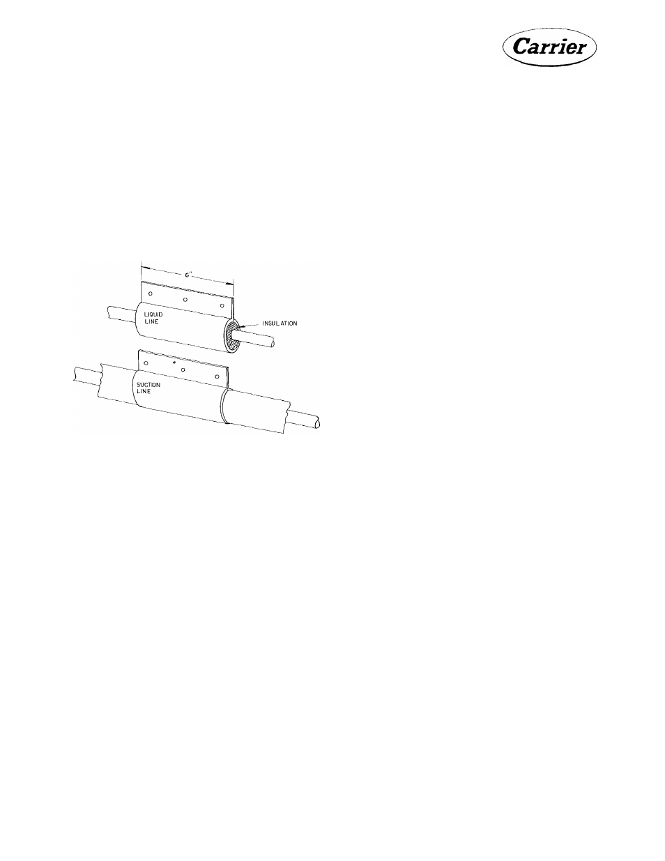
Elimination of Pipe Vibration
The liquid and suction lines are usually of soft
copper tubing. To absorb vibration, loop or
sweep tbe liquid and suction lines near the unit.
Fasten the tubing to walls or supports, using
vibration isolation type bangers as shown in
Fig. 17. Keep uninsulated lines away from hot
water or steam lines. Follow the piping prac
tices in Carrier System Design Manual, Part 3.
Fig. 17 - Refrigerant Line Hangers
Time Guard Control Operation
CONTROL CIRCUIT
This unit is equipped with controls which pro
vide automatic reset overload protection, time
delay in starting, and controlled cycling under
any cycling condition. Following shutdown of
the compressor for any reason (i.e., opening,
of the thermostat, functioning of a protective
device, power failure), the control permits re
starting of the compressor only after a five
minute period has elapsed. On normal starts,
the control will operate 15 seconds before start
ing the compressor.
The heart of the control is the cycle timer. The
cam on the cycle timer completes one revolu
tion in five minutes. Whenever the compressor
is stopped the timer motor will automatically
run until the cam lever is operated, which in
turn actuates the necessary switches. When this
sequence is completed, the cycle timer is pre
pared to start the unit.
Table 4 shows the normal operating sequence
of the timer circuit. This table can be helpful
in diagnosing electrical problems.
Operation of the control circuit is generally the
same on all voltage units. However, wiring se
quences for the individual controls may vary,
such as overloads and safety devices.
The following is a general description of the
operating sequence of the control circuit. Refer
to the schematic wiring diagrams as a guide.
The functions of this control accessory are:
1. To limit restart cycling of the compressor,
under any circumstance, to a minimum of
five minute intervals after stopping.
2. To allow time to run during normal "off
periods, thus utilizing this time as part of
the five minute timing interval described
above in No. 1.
3. To provide a 15 second delay on each com
pressor start before the compressor motor
starter is energized; to allow auxiliaries such
as condenser pump, condenser fan, chilled
water pump, etc. to be in operation before
the compressor starts. This feature will pre
vent nuisance cutouts due to momentary ac
tion of the high pressure switch or chilled
water flow switch during start-up.
20