Check refrigerant charge, 06d,07d, Carrier – Carrier 07D User Manual
Page 26: Installation
Attention! The text in this document has been recognized automatically. To view the original document, you can use the "Original mode".
06D,07D
INSTALLATION
Carrier
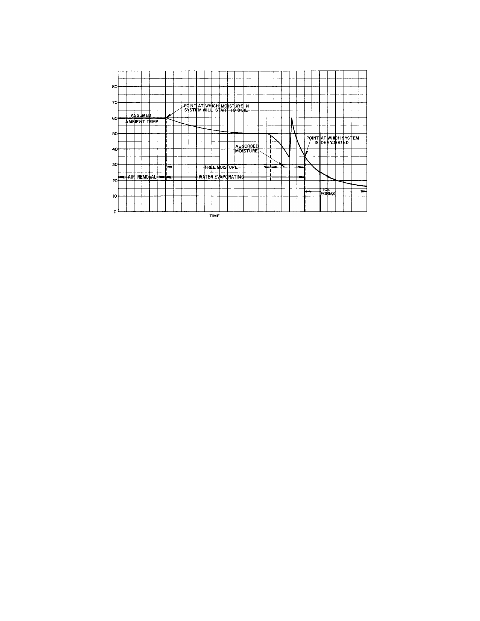
Fig. 21 - Dehydration Pull-Down Curve
valve open at least three minutes for each
reading. (Keep the valve closed at all other
times to decrease the amount of water the
pump must handle and hasten dehydration.)
When the pressure in the system drops to a
value corresponding to the vapor pressure of
the water in the indicator, the temperature
will start to drop. In the example shown in
Fig. 21, the ambient temperature and the
temperature of the water in the indicator
is 60 F. Starting at 60 F and 0 time, the
temperature of the water in the indicator
remains at 60 F until the pressure in the
system is pulled down to the pressure cor
responding to the saturation temperature of
the water (60 F). At this point the moisture
in the system will start to boil. The tem
perature drops slowly until the free mois
ture is removed, and then more rapidly until
the absorbed moisture is removed (35 F).
Dehydration is nearly completed at this point,
provided the ambient temperature remains
at 60 F or higher. If the ambient temperature
were lower than 60 F, ice might form before
moisture removal is complete.
3. Continue the dehydrating operation until the
vacuum indicator shows a reading of 35 F
which corresponds to a pressure of 0.204 in.
Hg absolute. This may take several hours. It
may be advantageous to run the pump all night.
4. With the pump still running, open the system
at a point farthest from the pump and admit
air thru a drier. Close system and repeat
Steps 2 and 3. Vapor in the system is thus
greatly diluted and almost completely re
moved by double dehydration.
5. After evacuation, turn off the pump suction
valve and break the vacuum by admitting
refrigerant.
6. Disconnect the pump and vacuum indicator.
CHECK REFRIGERANT CHARGE
After the system has been evacuated and dehy
drated, charge refrigerant in gas form into the
low side as follows:
1. Backseat the suction and discharge shut-off
valves. Install a gage in the discharge gage
port and turn the valve one turn from the
backseat position to allow pressure to reach
the gage.
2. Connect a refrigerant drum thru a drier and
tee connection with a compound gage, to the
suction gage port. Purge air from the lines
and tighten the connections.
3. Turn the suction shut-off valve a couple turns
from the backseat position and open the re
frigerant drum valve. Keep the refrigerant
drum in an upright position to prevent liquid
refrigerant from entering the compressor.
4. Start the compressor. See "INITIAL START
UP INSTRUCTIONS."
5. Check the refrigerant charge frequently while
charging, by observing the liquid line sight
glass. The refrigerant charge is sufficient
when flashing (bubbles) disappears. An al
ternate method of checking the charge is to
26