Toa VM-3000 Series User Manual
Page 93
93
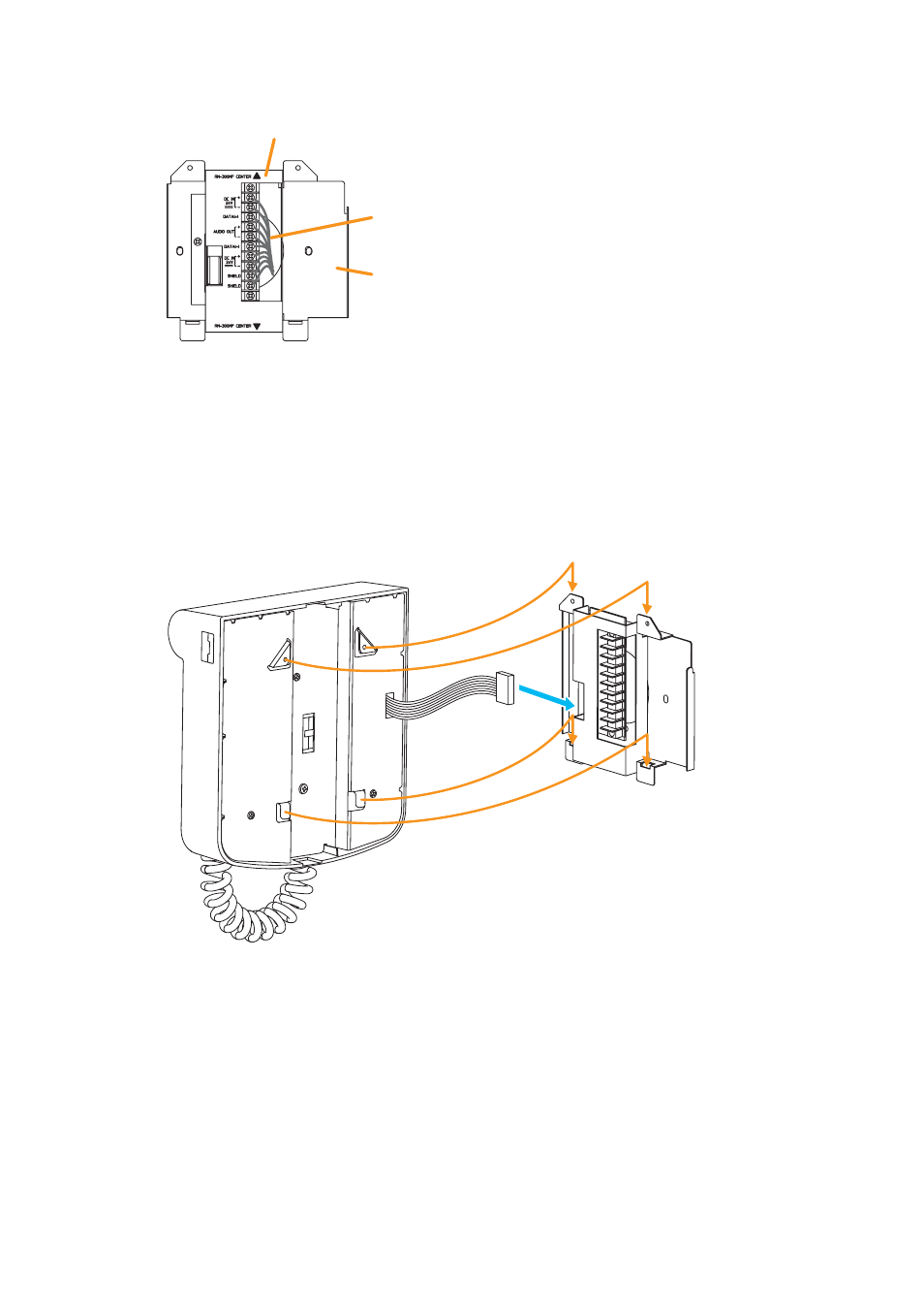
Step 2. Connect the link cable to the screw terminal block.
For cable connection, refer to "RM-300MF connection" on
Wall mount bracket unit
(supplied with the RM-300MF)
Bracket A
Bracket B
Link cable
Note
Put the link cable inside the Bracket A after
connection completion.
Do not allow the link cable to protrude.
The cable may be damaged if it protrudes when
the bracket unit is installed onto the wall.
Step 3. Plug the RM-300MF's connection cable into the connector port on the wall mount bracket unit.
Step 4. Attach the RM-300MF unit to the wall mount bracket unit.
Note
When attaching the RM-300MF unit, check that
the extension connector is not pinched.
4
Connection cable
RM-300MF
Wall mount bracket unit
(supplied with the RM-300MF)
3
See also other documents in the category Toa Receivers and Amplifiers:
- A-1803 (16 pages)
- A-1706 (12 pages)
- FS-7006PA (24 pages)
- CA-115 (2 pages)
- DA-250D CU (24 pages)
- DA-250F CU (24 pages)
- DA-550F CU (24 pages)
- S-D7802 (40 pages)
- A-2030 L (12 pages)
- A-230 CE-GB (12 pages)
- A-230 HV (8 pages)
- A-706 (12 pages)
- A-903MK2 (16 pages)
- M-9000M2 (163 pages)
- 9000M2 Series Quick Start (2 pages)
- BG-220 (16 pages)
- DA-250D CE301 (16 pages)
- DA-250F CE301 (20 pages)
- DA-550F CE301 (20 pages)
- M-9000M2 v.2.00 (155 pages)
- P-1812 (12 pages)
- P-2240 L (12 pages)
- P-9060DH (16 pages)
- P-906MK2 (16 pages)
- PA-3640VB (8 pages)
- RU-2001 (1 page)
- SS-9001 (2 pages)
- SV-200MA (4 pages)
- VM-2120 (60 pages)
- TA-102 (8 pages)
- VM-300SV (1 page)
- VM-3000 Series (90 pages)
- VM-3000 Series Read Me First (8 pages)
- VP-1061 Manual (12 pages)
- VP-1061 Installation (1 page)
- VR-1001B (1 page)
- W-906A Manual (12 pages)
- W-906A Service Manual (16 pages)
- WA-1822 (24 pages)
- WT-2100 (4 pages)
- WT-5100 (44 pages)