Vm-300sv connection – Toa VM-3000 Series User Manual
Page 125
125
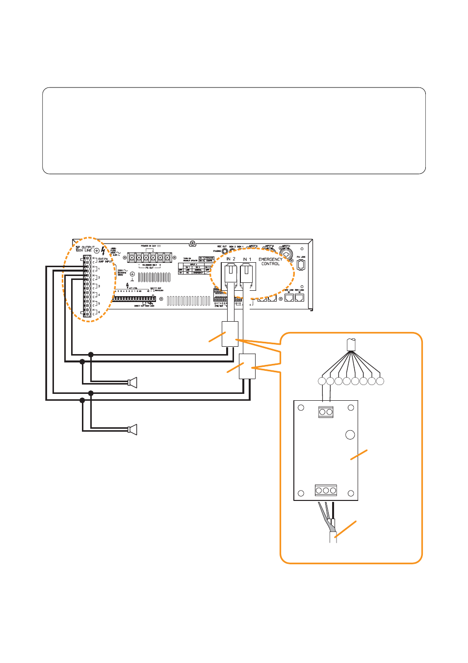
14.6. VM-300SV Connection
Speaker line failure can be detected with greater accuracy when the VM-300SV units are connected to the
VM-3000VA's or VM-3000E's Emergency control inputs 1 – 5.
Notes
• This function can be used only when all the versions of VM-3000VA firmware, VM-3000E firmware,
and VM-3000 Setting Software are 2.00 or later.
• Connect the VM-300SV between each speaker line end and the unit's Emergency control input
terminal.
• While a broadcast is being made through the speaker line with the VM-300SV installed, speaker line
failure function for that line cannot be performed.
• External attenuators cannot be used in the system with the VM-300SV installed.
The figure below shows a connection example to connect each one VM-300SV to the speaker lines 1 and 2.
VM-300SV
VM-300SV
VM-300SV
G
C
CN2
CN1
H
C
E
RJ45 connector
Pin No.
1 2
5
4
3
6 7 8
Speaker line
(cable end)
Note
Speaker line (E) may not be connected.
VM-3240VA/3360VA/3240E/3360E
Speaker
Speaker
Emergency control
inputs 1 – 4
Emergency control
input 5
Tip
Use a cable fitted with RJ45 connectors for connection to the Emergency control input terminal.
Shown above gives an example of Pin arrangement. (Refer to
"Terminal assignment to the emergency control
Note
"End of line" function must be assigned to the Emergency
control input terminals. But this function cannot be assigned to
the Emergency control input 6.
(Refer to "Emergency Control Input Settings" in "Event settings"
in the separate software instruction manual.)