System example 2, System outline – Toa VM-3000 Series User Manual
Page 8
8
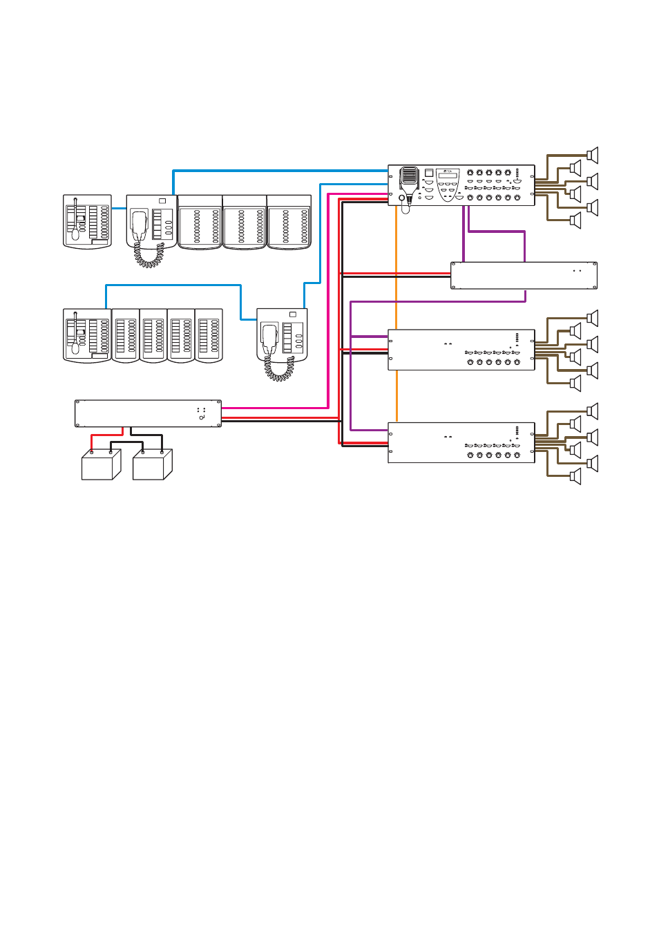
3.2. System Example 2
A standby amplifier is connected to this system, which is ideal for installation in factories and schools.
[System outline]
•
A 720 W integrated 1-channel emergency/general broadcast system with 18 outputs.
•
A VP-2241 standby amplifier is connected to the system. If the Voice Alarm System Amplifier should fail
during a general or emergency broadcast, it is automatically switched to the standby amplifier, allowing the
broadcast to continue uninterrupted.
•
Emergency broadcasts can be made even during power failures if the VX-2000DS Emergency Power
Supply is connected. However, general broadcasts are not possible.
RM-300MF
RM-320F
RM-300MF
Lead-acid Battery
VX-2000DS
VM-3240E
VM-3240E
RM-200M
RM-200M
RM-210
VM-3240VA
VP-2241
EXT. AMP INPUT
EXT. AMP
INPUT
EXT. AMP
INPUT
EXT. PA LINK
DC POWER
VM LINK
RM LINK 1
RM LINK 2
DC POWER
DS LINK
VM LINK
PA OUT
PA OUT