Vp-2241/2421 power amplifiers – Toa VM-3000 Series User Manual
Page 23
23
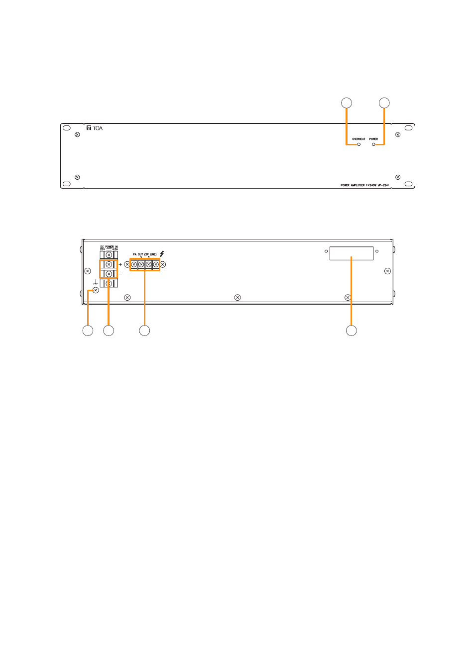
[Front]
[Rear]
1
2
3
4
5
6
1. Channel power indicator [POWER]
Lights green when the power is supplied with the
input module mounted.
• Off:
VP-200VX not installed
• Lights green: In-use status
• Lights red:
Standby status or DC fuse blowout
2. Overheat indicator [OVERHEAT]
If the internals of the power amplifier overheat, this
indicator lights yellow and the power amplifier's
operation is stopped.
3. Ground terminal
4. DC power inputs [DC POWER IN]
Connect to the VX-2000DS Emergency Power
Supply's DC POWER OUT terminal.
5. Output terminals [PA OUT (SP LINE)]
Connect to the power amplifier input terminal of
the VM-3240VA/3360VA or VM-3240E/3360E.
The speaker line output voltage can be changed
with an internal modification.
6. Module slot
Insert the VP-200VX Power Amplifier Input
module into this slot.
4.7. VP-2241/2421 Power Amplifiers
Two different configurations of power amplifiers can be used in the VM-3000 system: 240 W x 1 channel, and
420 W x 1 channel versions. Mount a VP-200VX Power Amplifier Input module to the module slot on the rear.