Toa DA-500F-HL CU User Manual
Operating instructions
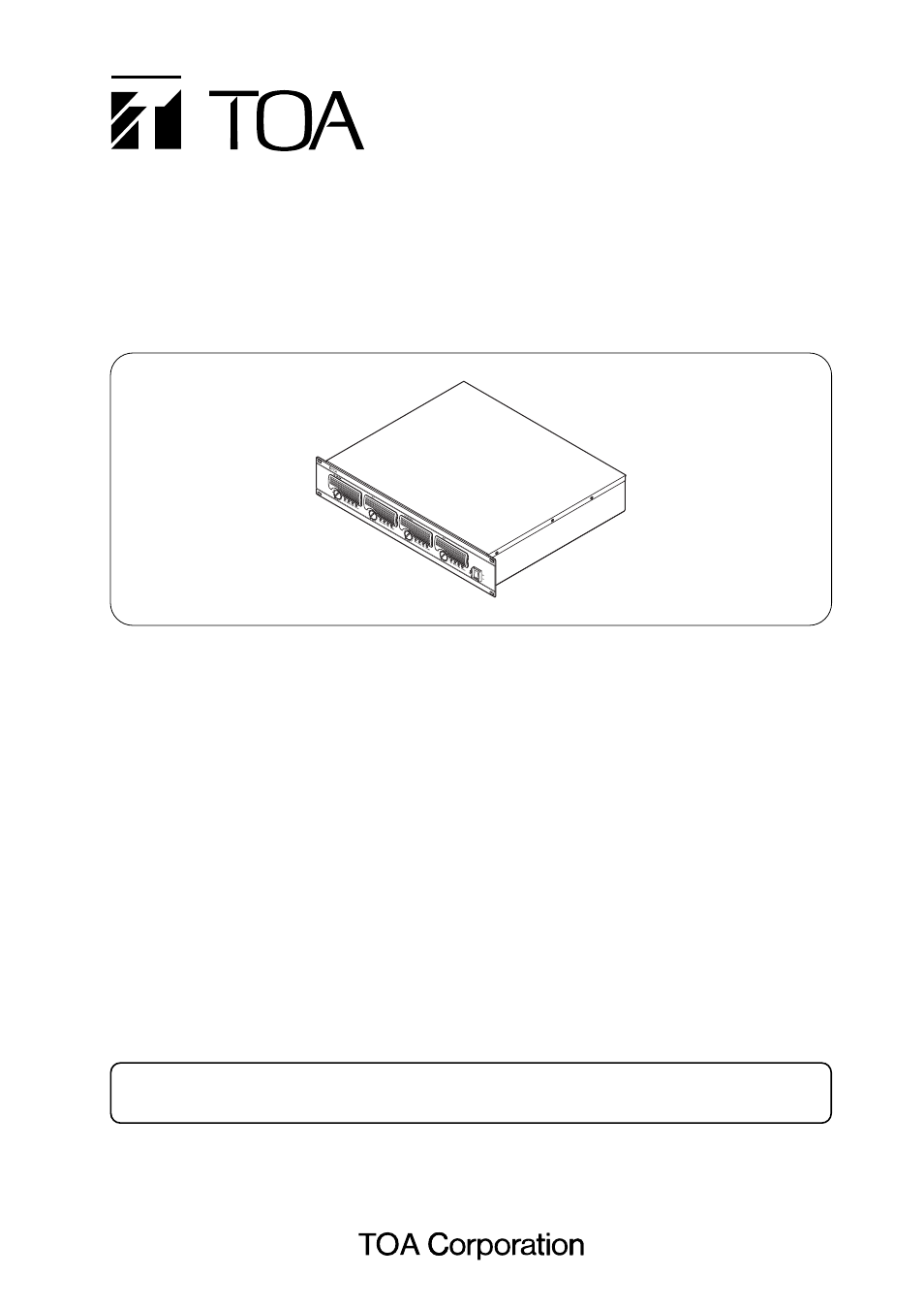
OPERATING INSTRUCTIONS
MULTICHANNEL POWER AMPLIFIERS
DA-550F CU
DA-500F-HL CU
Thank you for purchasing TOA's Multichannel Power Amplifier.
Please carefully follow the instructions in this manual to ensure long, trouble-free use of your equipment.
1. IMPORTANT SAFETY INSTRUCTIONS ............. 2
2. SAFETY PRECAUTIONS .................................... 4
3. GENERAL DESCRIPTION .................................. 8
4. FEATURES .......................................................... 8
5. HANDLING PRECAUTIONS ............................... 8
6. INSTALLATION PRECAUTIONS ........................ 9
7. NOMENCLATURE AND FUNCTIONS
Front .................................................................... 10
Rear .................................................................... 11
8. SETTINGS AND CONNECTIONS ...................... 13
8.1. Switch Settings and Speaker Connections ...... 14
9. REMOVABLE TERMINAL PLUG CONNECTION ... 16
10. INPUT SENSITIVITY SETTING .......................... 17
11. PROTECTION OPERATION LIST ..................... 17
12. TAMPER-PROOF CAP ATTACHMENT ............ 18
13. CLEANING THE FILTER .................................... 18
14. DIMENSIONAL DIAGRAM ................................. 18
15. BLOCK DIAGRAMS
15.1. DA-550F ..................................................... 19
15.2. DA-500F-HL ............................................... 19
16. HOW TO USE THE CONTROL/MONITOR TERMINALS
16.1. Control Terminal (Input) ............................. 20
16.2. Monitor Terminal (Output) .......................... 20
16.3. About Pin 7 of the Control/Monitor Terminals ... 21
16.4. Terminal Pin Arrangement ......................... 21
16.5. Connection Cable and Maximum Cable Length ... 21
16.6. RJ45 Connector's Pin Arrangement and
Cable Color Codes ..................................... 22
17. SPECIFICATIONS
17.1. DA-550F CU ............................................... 23
17.2. DA-500F-HL CU ......................................... 24
TABLE OF CONTENTS
An all-pole mains switch with a contact separation of at least 3 mm (0.12") in each pole
shall be incorporated in the electrical installation of the building.