The curved guidance mode, Applying multiple headland circuits – TeeJet SmartPad II User Guide User Manual
Page 105
SmartPad II
Software Version 4.03
Chapter 3 - Real-Time Guidance
3-51
The Curved Guidance Mode
The Curved Guidance Mode
This section describes how to run swath guidance when the Headland guidance pattern option is selected. The Head-
land option is selected when the operator wants to drive several circuits around the field boundary and be guided
around all circuits that occur after the first circuit. Once several headland circuits have been completed, the operator
then has the choice of switching, in real-time, to Parallel mode. The Headland option is also selected when a user
wants to do product application on terraced fields. In Headland curved guidance mode, the operator can pull along
side any previous applied swath and be guided parallel to that swath.
In this section the operator wants to apply two headland passes to the field and then switch to Parallel mode and apply
the remainder of the field with straight-line parallel swath guidance. After the first headland circuit the operator will
pull parallel to the first circuit swath and begin applying the second circuit while being guided parallel to the first cir-
cuit.
Applying Multiple Headland Circuits
Figure 3-68 shows the SmartPad II View Page when the Curved guidance mode is selected. Notice in this figure that
the user is in Curved guidance mode (top button in button bar) and still has the option to mark the A point for straight-
line parallel swath guidance. This feature makes it easier for the operator to Mark the A and B points while in curved
mode applying the headlands. It is always best to mark the A and B points for parallel straight-line guidance while
driving along a straight edge of a field. The operator marked the A and B points along the South boundary of the field,
see Figure 3-69.
The operator will remain in curved guidance mode until the curved guidance button is pressed, top button in Figure 3-
68. The A and B points are only required for the straight-line guidance mode. The curved guidance mode does not
require the A and B points.
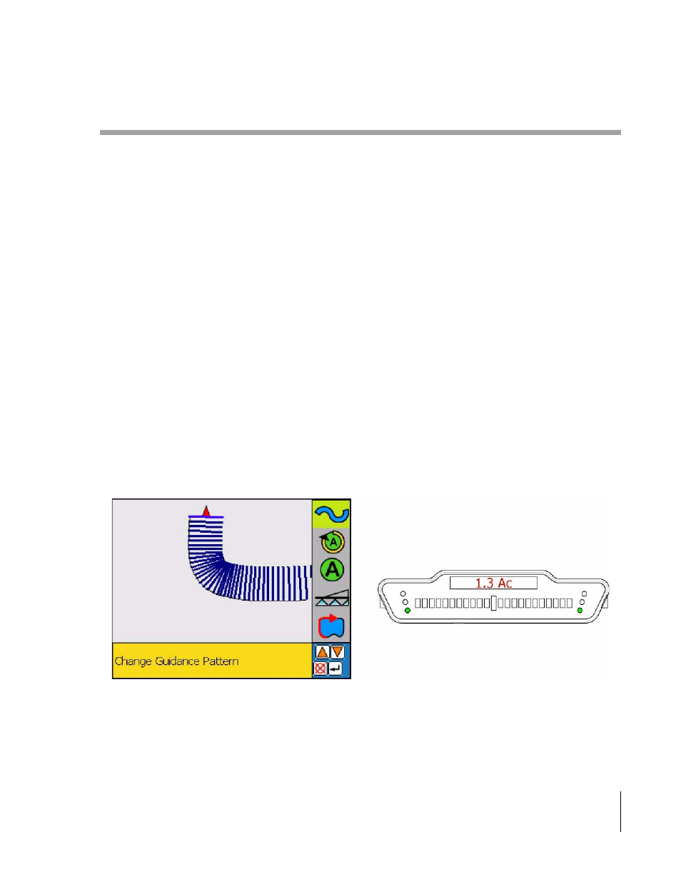
Figure 3-69 shows the operator just finishing the first headland circuit. Once the operator pulls along side the first
headland circuit, curved guidance will automatically start. The operator will now be able to drive the second headland
circuit parallel to the first circuit by following the guidance information displayed on the lightbar.
Figure 3-68: The View Page in Headland Pattern