Maintenance and service (cont'd), 3 troubleshooting, 2 maintenance procedures (cont'd) – Reznor B Unit Installation Manual User Manual
Page 38: 10 fan, limit, & eco controls (cont'd)
Form I-F/B, P/N 98126 R21, Page 38
Instructions for replacing fan or limit control and ECO device:
1. Turn off the electric power and shut off the gas supply.
2. Remove the outer left side panel left when facing the back of the unit).
Remove the access panel.
3. Remove defective controls. Install new controls in the same
mounting holes. Use only factory-authorized replacement parts.
4. Replace access panel and side panel.
5. Turn on the electric power and the gas supply.
6. Relight following the lighting
instructions on the heater.
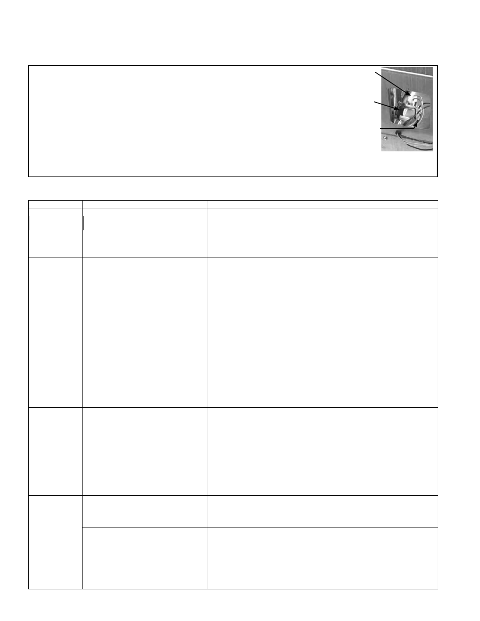
Fan Control
ECO Device
Limit
Control
FIGURE 48 - Side Panel and
Access Panel Removed showing Fan Control,
Limit Control, and ECO (See NOTE on page 37.)
TROUBLE
PROBABLE CAUSE
REMEDY
Pilot will not light
(match-lit pilot
system)
1. Pilot valve turned off.
1. Open manual valve.
2. Air in gas line.
2. Disconnect pilot line at shutoff. Bleed air from gas supply line.
3. Incorrect lighting procedure.
3. Follow instructions o the heater.
4. Dirt in pilot orifice.
4. Remove and clean with compressed air or solvent (do not ream).
5. Gas pressure too high or too low.
5. Check gas supply pressure. (See Paragraph 6.1).
6. Bent or kinked pilot tubing.
6. Replace tubing.
7. Failed ECO device.
7. Replace ECO device (See Paragraph 10.2.9).
Pilot will not light
(spark ignition)
1. Manual valve not open.
1. Open manual valve.
2. Power not turned on or thermostat not calling
for heat.
2. Turn on power. Check fuse/circuit breaker in disconnect switch. If unit is equipped
with unit-mounted disconnect switch, check circuit breaker. (See Paragraph 7.) Check
thermostat setting.
3. Air in gas line.
3. Bleed gas line.
4. Dirt in pilot orifice.
4. Remove and clean with compressed air or solvent (do not ream).
5. Gas pressure too high or too low.
5. Adjust supply pressure. (See Paragraph 6.1).
6. Bent or kinked pilot tubing.
6. Replace tubing.
7. Pilot valve does not open.
7. If 24 volt available at valve, replace valve.
8. No spark:
8.
a) Loose wire connections
a) Be certain all wires connections are solid.
b) Transformer failure.
b) Be certain 24 volts is available.
c) Incorrect spark gap.
c) Maintain spark gap at .100".
d) Spark cable shorted to ground.
d) Replace worn or grounded spark cable.
e) Spark electrode shorted to ground.
e) Replace pilot if ceramic spark electrode is cracked or grounded.
f) Drafts affecting pilot.
f) Make sure all panels are in place and tightly secured to prevent drafts at pilot.
g) Ignition control not grounded.
g) Make certain ignition control is grounded to furnace chassis
h) Faulty ignition controller.
h) If 24 volt is available to ignition controller and all other causes have been eliminated,
replace ignition control.
9. Optional lockout device interrupting control
circuit by above causes.
9. Reset lockout by interrupting control at thermostat.
10. Faulty blocked vent switch.
10. Correct venting problem; reset switch (see Paragraph 8.2).
Pilot lights, main
valve will not open
(all manual valves
are open,
match-lit pilot)
1. Power not turned on or thermostat not calling
for heat.
1. Turn on power. Check fuse/circuit breaker in disconnect switch. If unit is equipped
with unit-mounted disconnect switch, check circuit breaker. (See Paragraph 7.2.) Check
thermostat setting.
2. Circuit to magnetic valve open.
2. Check wiring and connections at transformer and thermostat.
3. Faulty transformer
3. Replace transformer.
4. Faulty or dirty thermocouple or safety pilot
switch or failed ECO device.
4. Clean and test with millivolt meter or test kit. Replace defective part.
5. Faulty thermostat (see manufacturer's
instructions)
5. Replace thermostat
6. Faulty magnetic valve
6. Replace valve or magnetic heat,
7. High gas pressure
7. Maximum gas supply pressure is 14"w.c. (See Paragraph 6.1.)
8. Activated blocked vent switch
8. Correct venting problem; reset switch (see Paragraph 8.2).
Pilot lights, main
valve will not open
(Spark Ignition
system)
1. Manual valve not open.
1. Open manual valve.
2. Main valve not operating.
2.
a) Defective valve.
a) If 24 volt is measured at valve connections and valve remains closed, replace valve.
b) Loose wire connections.
b) Check and tighten all wiring connections.
3. Ignition control does not power main valve.
3.
a) Loose wire connections.
a) Check and tighten all wiring connections
b) Flame sensor grounded (pilot lights - spark
continues)
b) Be certain flame sensor lead is not grounded or insulation of ceramic is not cracked.
Replace sensor as required.
c) Gas pressure incorrect.
c) Supply pressure should be 5 - 14" w.c. for natural gas and 11- 14" w.c. for propane gas.
d) Cracked ceramic at sensor.
d) Replace sensor.
e) Faulty ignition controller.
e) See Paragraph 10.2.3. If all checks indicate no other cause, replace ignition controller.
DO NOT ATTEMPT TO REPAIR IGNITION CONTROLLER. THIS DEVICE HAS NO FIELD
REPLACEABLE PARTS.
10.3 Troubleshooting
10. Maintenance
and Service
(cont'd)
10.2 Maintenance Procedures (cont'd)
10.2.10 Fan, Limit, & ECO Controls (cont'd)