5 pilot and ignition systems, 6 burner air adjustment – Reznor B Unit Installation Manual User Manual
Page 31
Form I-F/B, P/N 98126 R21, Page 31
NOTES:
Natural gas units
manufactured prior to
9/2007 may have Option
AH2, which is a spark
ignited intermittent safety
pilot system with recycling
pilot without lockout.
Units manufactured prior to
8/2008 may have a match-
lit pilot.
8.5 Pilot and Ignition Systems
The pilot on Model F and B unit heaters is a spark ignited intermittent safety pilot sys-
tem with lockout (Option AH3). The ignition controller in the spark pilot system provides
the high voltage spark to ignite the pilot gas and also acts as the flame safety device.
After ignition of the pilot gas, the control electronically senses the pilot flame. (A sepa-
rate solid metal probe in the pilot burner assembly is employed for the flame sensing
function. A low voltage electrical signal is imposed on that metal probe which is electri-
cally isolated from ground. When the pilot flame impinges on the flame sensing probe,
the flame acts as a conduction path to ground. The pilot flame rectifies and completes
the DC circuit. The ignition controller acknowledges the flame and energizes the main
gas valve.)
A lockout device stops the gas flow to the pilot if the pilot fails to light in 120 seconds.
The spark pilot system with lockout has a 1-hour retry or requires manual reset by inter-
ruption of the thermostat circuit.
8.6 Burner Air Adjustment
Model F and B unit heaters have individually formed steel burners with accurately
die-formed ports to give controlled flame stability without lifting or flashback with either
natural or propane gas. The burners are lightweight and factory mounted in an assem-
bly which permits them to be removed as a unit for inspection or service.
All sizes of Model F and B unit heaters that are equipped with standard aluminized
burners are designed to operate without burner air shutters when fueled with either
natural or propane gas. However, Sizes 165 through 400 equipped with optional stain-
less steel burners (Option AD2) require air shutters (Option AE1) when used with pro-
pane gas (Option AA2).
Optional air shutters, either factory or field installed, are available for any size model for
use where unusual conditions cause excess primary aeration.
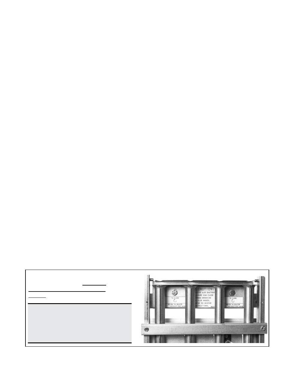
Before making any adjustments to the air shutters, allow the heater to operate for about
fifteen minutes. The air shutter adjustment screws can be reached by opening the bot-
tom panel. (Remove the two screws located at the rear of the bottom panel and allow
the panel to hinge down from the front.) The adjustment screws for the air shutters are
visible at the rear of the burner rack. See
FIGURE 34.
When making the adjustment, close the air shutters no more than is necessary to elimi-
nate the problem condition.
Observe the flame for yellow-tipping. A limited amount of yellow-tipping is permissible
for liquefied petroleum gases. Other fuels should not display any yellow-tipping.
Two adjustment screws are used (See
FIGURE 34). Rotating the screws clockwise
closes the shutters, reducing the primary air supply. Counterclockwise rotation opens
the shutters, increasing the primary air supply. The two adjustment screws should be
rotated alternately to open or close the shutters. Attempting to gain adjustment by not
alternating between the two screws may cause the shutters to bind.
After proper adjustment has been completed, eliminating the problem condition, close
the bottom panel and replace the retaining screws.
FIGURE 34 - Air Shutter
Adjustment Screws -- Alternate
turning screws when adjusting
shutter.
DANGER: Failure to install and/or
adjust air shutters according to
directions could cause property
damage, personal injury, and or
death.