Mechanical (cont'd), 2 venting, 1 gas piping and pressures (cont'd) – Reznor B Unit Installation Manual User Manual
Page 16
Form I-F/B, P/N 98126 R21, Page 16
6.2 Venting
3. With the manual valve positioned to prevent flow to the main burners, connect
a manometer to the 1/8” pipe outlet pressure tap in the valve. Use a fluid-filled
manometer that is readable to the nearest tenth of an inch w.c.
4. Remove the cap from the pressure adjusting screw and adjust the manifold
pressure to the pressure setting selected from the table. Cycle the main burners
once or twice to properly seat the adjustment spring in the valve.
Re-check the pressure. If necessary, re-adjust the pressure. When the pressure
is correct, remove the manometer and replace the cap. Check for leaks at the
pressure tap fitting.
5. With the heater operating determine that the inlet pressure to the heater for
natural gas is between 5 and 14 inches w.c. and for propane between 10 and 14
inches w.c. Take this reading as close as possible to heater (Most heaters are now
equipped with gas valves that have an inlet pressure tap.)
If the inlet pressure
is not within the specified range, the inlet pressure must be corrected and
Steps 3 and 4 repeated.
6. Find the High Altitude Adjustment label in the plastic bag that contained these
instructions. Using a permanent marker, fill-in the pressure setting. Adhere the
label on the heater near the gas valve so that it is conspicuous to someone
servicing the valve and/or the heater.
6.1.2 Manifold or
Orifice Pressure
Settings (cont'd)
DANGER: Failure to provide proper venting could result in death,
serious injury, and/or property damage. This heater must be installed
with a vent connection and proper vent to the outside of the building.
Install vent in accordance with Part 7, Venting of Equipment, of the
National Fuel Gas Code, ANSI Z223.1 (latest edition) or applicable
provision of national, state or local codes. A Canadian installation
must be in accordance with the CSA B149.1 and B149.2, Installation
Code for Gas Burning Appliances and Equipment, and applicable
local codes. Also, follow venting recommendations listed below.
Safe operation of any gravity-vented gas equipment requires a properly
operating vent system, correct provision for the combustion air (See
Paragraphs 2.2 and 4.1) and regular maintenance and inspection. See
Hazard Levels, page 2.
6.2.1 Vent Outlet
Sizes
6.2.2 Venting
Requirements - All
Models
1. Provide a minimum clearance of 18" (457mm) between the drafthood relief
opening and any obstruction. Do not expose the relief opening to wind drafts from
any source such as from an overhead door or adjacent air handling equipment.
2. The unit is equipped with a built-in draft diverter, consequently an external draft
diverter
MUST NOT be installed in the vent connector or any internal alterations
made. Do not install a manual damper or other fixed restriction in the vent
connector.
A gravity-vented unit heater manufactured after August 7, 2008, MUST be installed
with either an automatically controll
ed motorized vent damper (Option AV7) or
power venting (Option CA).
3. Vent pipe should be a minimum of 26 gauge galvanized steel or other non-
corrosive material. Double wall, Type B vent such as Metalbestos or Amerivent
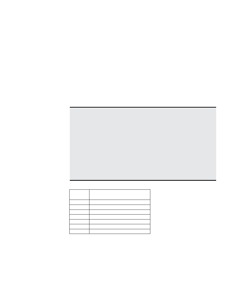
Heaters have the following vent outlet sizes:
Model
Size
Size Configuration of Horizontal/
Vertical Vent Outlet
25 - 50
4" Round
75
5" Oval
100
6" Oval
125
7" Oval
165 - 200
8" Oval
250 - 300
10" Oval
400
12" Oval
6. Mechanical
(cont'd)
6.1 Gas Piping
and Pressures
(cont'd)
NOTE: Standard units
manufactured prior to 10/89 (Serial
No. Date Code prior to AOJ) have
a round fixed vertical vent outlet in
the size listed. Units manufactured
prior to 10/89 with Option BT1
have the horizontal/vertical vent
outlet.