Maintenance and service (cont'd), Caution: eye protection is recommended – Reznor B Unit Installation Manual User Manual
Page 34
Form I-F/B, P/N 98126 R21, Page 34
10.2.2 Burner Rack
Removal
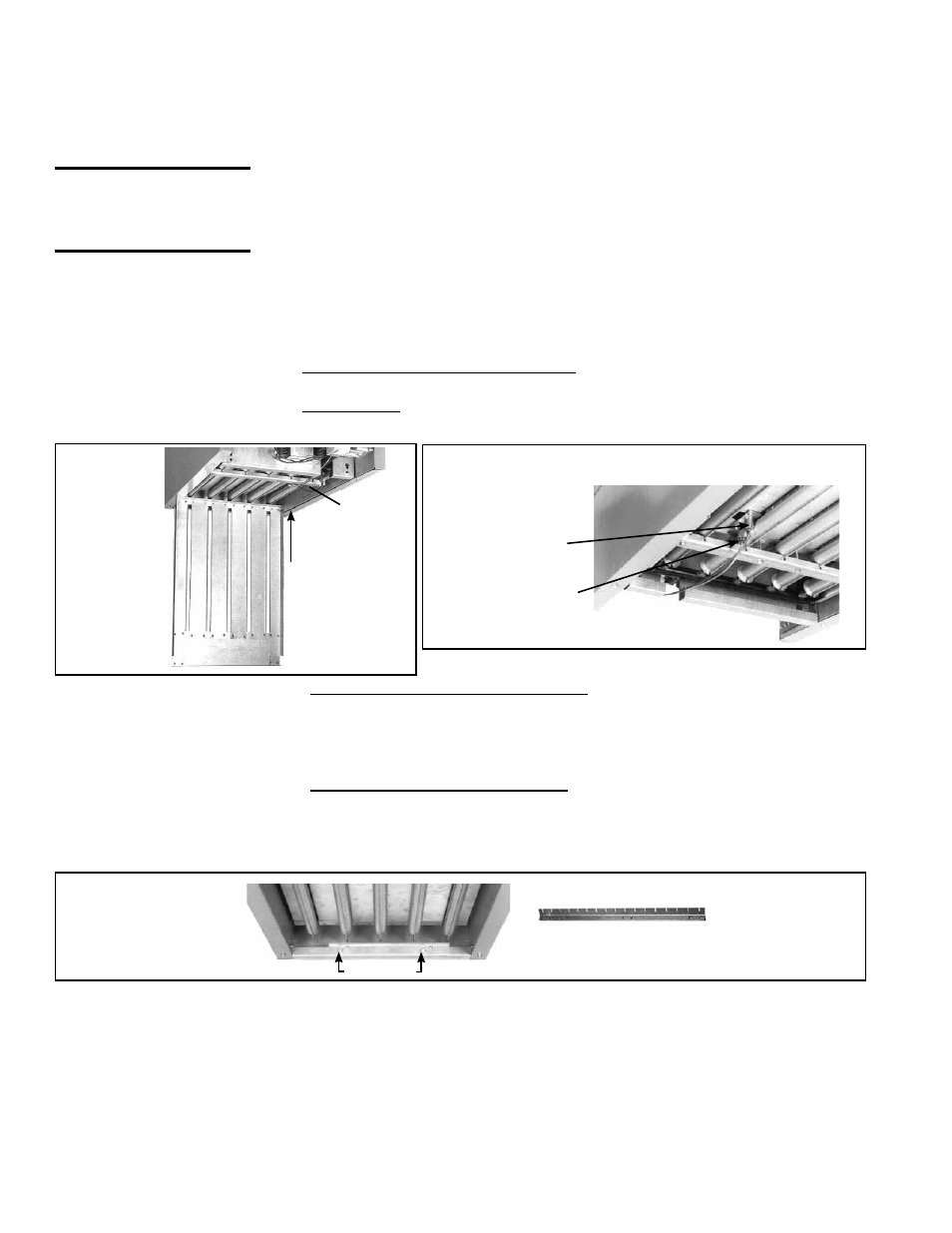
FIGURE 37 - Pilot Location
Thermocouple
(match-lit pilot)
Pilot Tubing
Push hinge
pin to remove
bottom panel.
Pilot
Location
Burner Rack Support with Indexing
NOTE: Burner Rack Support on units
manufactured prior to 8/1991 was not indexed.
FIGURE 38 - Burner
Rack Support and
Retaining Screws
FIGURE 36
- Bottom
Access
Panel Open
CAUTION: Eye
protection is
recommended.
7A. Heaters manufactured beginning 8/91 (Serial No. Date Code AQH) - The
burner rack support is indexed as illustrated in
FIGURE 38. While supporting the
burner rack, remove the screws (two or three) that hold the burner rack support.
(For screw location, refer to
FIGURE 38.) Remove the burner rack support
allowing the burner rack assembly to swing down (See
FIGURE 39).
7B. Heaters manufactured prior to 8/91 (Serial No. Date Code AQH) Loosen the
sheetmetal screws (two or three) located at the front of the burner rack assembly.
See
FIGURE 38. These screws retain the burner rack support. While supporting
the burner rack assembly, slide the burner rack support and remove it from the
screws, allowing the burner rack assembly to swing down (See
FIGURE 39).
8. To Remove the Burner Rack - With the burner rack assembly "hanging" down, lift
up on the rear and slide the assembly up and out of the manifold support brackets.
See
FIGURES 39-41.
Screws
These unit heaters have a convenient bottom access panel. The pilot is attainable with
the bottom panel open. With the access panel removed, the burner rack assembly will
hinge down for removal. Use the following step-by-step instructions for removal of the
bottom access panel and the complete burner rack assembly.
Instructions for Burner Rack Removal (See FIGURES 36-41.)
1. Shut the gas supply off ahead of the combination valve.
2. Turn off electric supply.
3. Remove the two sheetmetal screws located at the rear of the bottom panel.
4. Allow bottom panel to hinge down from the front.
5. Push in one of the two spring-loaded hinge pins located at the front of the bottom
panel (inside), and completely remove the bottom panel.
6. The bottom of the pilot is now visible. Do the following:
(a) Disconnect the pilot tubing from the pilot burner.
(b) For match-lit pilot (mfgd prior to 8/2008), disconnect the thermocouple from the
valve.
(c) For spark pilot, disconnect the flame sensing wire and high tension (spark) lead
from the ignition controller.
9. To remove the individual burners (FIGURE 42):
a. Remove the flash carryover (one screw per burner).
b. With the burner rack upside down, remove the sheetmetal screws (located at the
rear) that retain the burner hold down.
c. Lift the rear of the burner upward slightly and pull back, removing the individual
burners.
10. MAINTENANCE AND SERVICE (cont'd)